





Description
Engineering Value
The module provides a direct DCS interface for temperature sensors used in process equipment, utility systems, furnaces, heat exchangers, and rotating machinery auxiliaries. Its 0–320 Ω input range covers common 100 Ω platinum RTDs and selected nickel RTD configurations.
Two-, three-, and four-wire connection methods are supported. The wiring method must match the installed termination assembly and the control-system configuration; changing the number of wires without updating the termination arrangement can introduce lead-resistance error.
Technical Specifications
| Parameter | Specification |
|---|---|
| Input type | Resistance temperature detector |
| Supported sensor materials | Platinum and nickel |
| Input channels | Eight isolated and independent channels |
| Input resistance range | 0–320 Ω per channel |
| Nominal platinum RTD | 100 Ω at 0°C |
| Nominal nickel RTD | 235 Ω at 0°C |
| Wiring configurations | Two-wire, three-wire, and four-wire |
| Sensor excitation | 0.75 mA DC |
| Resistance accuracy | ±0.025% of span, approximately ±0.08 Ω |
| Temperature conformity | ±0.25°C |
| Temperature coefficient | ±25 ppm/°C |
| Reference input | No separate thermocouple reference-junction channel |
| Fieldbus | Redundant I/A Series Fieldbus |
| Redundant input voltage | 26–42 VDC |
| Maximum power consumption | 9 W |
| Maximum heat dissipation | 9 W |
| Isolation withstand | 600 VAC for one minute between a channel and ground, or between channels |
| Operating temperature | 0–60°C, or 32–140°F |
| Storage temperature | −40–70°C, or −40–158°F |
| Relative humidity | 5–95%, noncondensing |
The published FBM03 specification identifies platinum, nickel, and multiple RTD wiring configurations. It also lists the 0–320 Ω measurement range, 0.75 mA sensor current, redundant 26–42 VDC input, 9 W maximum consumption, and 600 VAC isolation withstand capability.
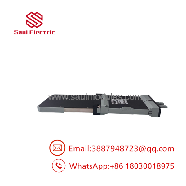
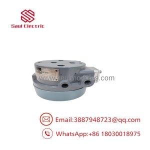
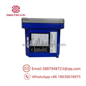
FBM03
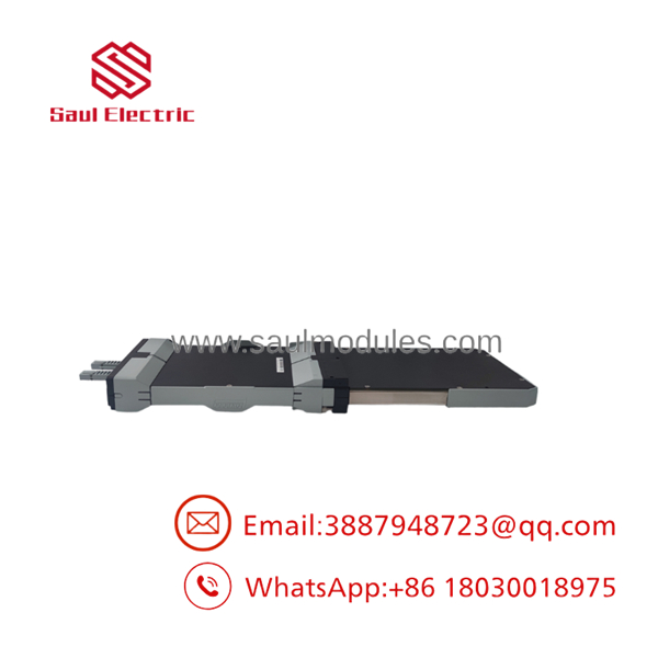
FBM03
Field Application
A chemical plant had eight reactor-jacket RTDs connected to an FBM03. After a module replacement, six channels appeared normal, but two showed temperatures approximately 8°C higher than a calibrated handheld reference. The technician initially suspected bad sensors. The actual issue was a three-wire termination mismatch: the replacement had been configured for a different lead arrangement, causing the resistance of the field wiring to be interpreted as process temperature.
The correction required restoring the original RTD wiring configuration, checking the termination assembly, and verifying each channel with a precision resistance simulator. The field sensors did not need to be replaced.
Typical applications include:
- Reactor-jacket temperature monitoring in batch chemical processing.
- Bearing and winding temperature measurement on large motor-driven pumps.
- Feedwater and condensate temperature monitoring around boiler heat exchangers.
- Furnace zone and heat-treatment equipment temperature acquisition.
- Compressor lube-oil and seal-system RTD monitoring.
- Distillation-column tray or reboiler temperature measurement.
QA and Testing SOP
A meaningful FBM03 inspection should verify both the analog input circuit and I/A Series communication:
- Record the complete part number, serial number, revision, and termination assembly.
- Inspect the enclosure, backplane connector, Fieldbus connectors, status indicators, and retaining hardware.
- Apply controlled redundant DC power within the 26–42 VDC range.
- Confirm startup diagnostics and redundant Fieldbus communication.
- Simulate 100 Ω platinum RTD values at low, midpoint, and high points.
- Test representative two-wire, three-wire, and four-wire configurations when the test fixture permits.
- Verify channel-to-channel isolation and check for unexpected resistance paths.
- Test nickel RTD scaling if that configuration is required by the application.
- Confirm the DCS receives stable values without excessive noise, dropouts, or channel faults.
- Record measured resistance, calculated temperature, configuration data, and test equipment calibration status.
For new-surplus inventory, “unused” should not be confused with “calibrated.” The module may have remained in storage for years, so a seller should provide a functional test record rather than relying only on a power-up photograph.
Veteran’s Tech Trap Guide
⚠️ Trap 1: Substituting FBM02 for FBM03.
FBM02 is associated with thermocouple/mV inputs, while FBM03 is an RTD input module. They are not interchangeable simply because both measure temperature.
⚠️ Trap 2: Ignoring lead compensation.
Two-wire RTD connections include lead resistance in the measurement. Three-wire circuits compensate for lead resistance only when wired correctly, and four-wire circuits require the appropriate termination path.
⚠️ Trap 3: Mixing sensor standards.
A 100 Ω platinum RTD and a 235 Ω nickel RTD do not use the same linearization. Confirm sensor material, nominal resistance, and temperature curve in the DCS database.
⚠️ Trap 4: Overlooking termination hardware.
The module, baseplate, termination assembly, and Fieldbus arrangement function as a system. A visually similar terminal assembly may have different pin assignments or supported wiring methods.
PRO TIP: Measure the installed RTD resistance at the cabinet before disconnecting the old module. That single reading often identifies an open sensor, a shorted pair, a wrong sensor type, or an unexpected lead-resistance problem.
Dynamic FAQ
What type of input does the FBM03 accept?
It accepts RTD resistance signals from platinum and nickel sensors. The nominal sensor values identified in the specification are 100 Ω platinum at 0°C and 235 Ω nickel at 0°C.
How many sensors can one handle?
The module provides eight independent RTD input channels. Each channel is intended for one field sensor.
Can the use three-wire RTDs?
Yes. Two-wire, three-wire, and four-wire RTD configurations are supported, but the termination assembly and DCS configuration must match the wiring method.
Does support thermocouples?
No. is the RTD interface module. Thermocouple and millivolt applications generally require an appropriate thermocouple/mV FBM, such as FBM02 or another approved module, depending on the I/A Series generation.
What should be verified before ordering a replacement?
Confirm the complete hardware part number, module revision, I/A Series system generation, termination assembly, Fieldbus configuration, sensor material, nominal resistance, and required wiring method. Also check whether the plant requires a specific approved revision.
How should new-surplus or refurbished units be documented?
The seller should provide serial-number photos, connector and housing photographs, a power-up record, redundant Fieldbus verification, and resistance-simulation results for representative channels. The warranty should define repair or replacement coverage, return terms, testing status, and whether compatibility with the buyer’s termination hardware is guaranteed.

 Start Chat


