





Description
Engineering Value
FBM07 modules are used for equipment status, permissive logic, limit-switch monitoring, alarm contacts, and sequence-of-events applications. A single module provides 16 field input channels while maintaining isolation between channel pairs and ground.
The same module family can be configured for contact sensing or DC voltage monitoring. That flexibility is useful in older plants where some field devices provide dry contacts while others provide a powered DC status signal. The exact terminal assembly and module option must match the selected input mode.
Technical Specifications
| Parameter | Specification |
|---|---|
| Input function | Contact sensor or DC voltage monitor |
| Number of channels | 16 independent channels |
| Contact input state | Open = off; closed = on |
| Contact open-circuit voltage | 24 VDC ±10% |
| Contact short-circuit current | 2.5 mA maximum |
| Contact ON-state resistance | 1 kΩ maximum |
| Contact OFF-state resistance | 100 kΩ minimum |
| DC voltage ON-state range | 15–130 VDC |
| DC voltage OFF-state range | 0–5 VDC |
| DC voltage input current | Approximately 2.2 mA at 5–130 VDC |
| DC source resistance | 1 kΩ maximum for ON; 100 kΩ minimum for OFF |
| Input filter times | 4, 8, 16, or 32 ms |
| Channel isolation | Isolation between channel pairs and ground |
| Isolation withstand | 1,250 VAC for one minute between a channel and ground; 1,250 VAC between channel pairs |
| Module power input | Redundant 26–42 VDC |
| Power consumption | 7 W maximum for FBM07 alone; 12 W maximum with one expansion module |
| Communication | Redundant Fieldbus through the main module |
| Channel indication | One status LED per input channel on the termination assembly |
| Operating temperature | 0–60°C, or 32–140°F |
| Storage temperature | −40–70°C, or −40–158°F |
| Relative humidity | 5–95%, noncondensing |
| Environmental classification | ISA S71.04 Class G3 harsh environment |
| Approximate mass | 1 kg, or 2.2 lb |
The module’s channels are isolated in pairs rather than individually isolated from one another. For example, channels 1 and 2 share a common isolation group, while channels 3 and 4 form the next group. Hazardous and nonhazardous voltages must not be mixed within the same channel pair.
Field Application
A refinery flare-panel upgrade required the DCS to monitor sixteen field contacts, including pilot-gas pressure switches, flame-detector permissives, damper limit switches, and emergency shutdown feedback. The replacement FBM07 powered up correctly, but several inputs remained permanently active.
The technician found that the old installation used dry-contact sensing, while the replacement wiring had been treated as externally powered DC voltage monitoring. The field contacts were being evaluated against the wrong input circuit. After restoring the correct contact-sensor configuration and checking the termination assembly, the input states tracked the field devices correctly.
Niche applications include:
- Emergency shutdown valve limit-switch feedback.
- Fired-heater flame permissive and burner-management status contacts.
- Turbine lube-oil pressure-switch and overspeed relay monitoring.
- Pump motor starter auxiliary contacts and local/remote selector status.
- Boiler fan damper limit switches and combustion-air permissive circuits.
- Sequence-of-events monitoring for interlock transitions and trip indications.
For time-sensitive events, confirm that the selected application program and filter setting meet the plant’s sequence-of-events requirements. A 32 ms filter may reject contact bounce, but it can also suppress short-duration events.
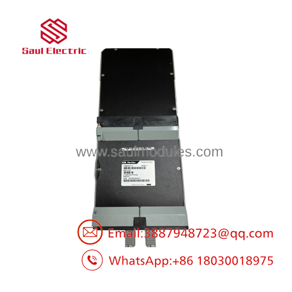
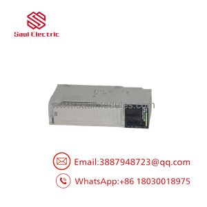
FBM07
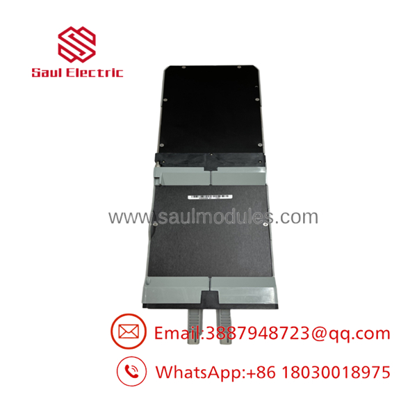
FBM07
QA and Testing SOP
A proper FBM07 test must identify whether the unit is configured as a contact sensor or a DC voltage monitor:
- Record the full module part number, suffix, revision, serial number, and termination assembly.
- Inspect the housing, backplane connector, Fieldbus connection, retaining hardware, and termination blocks.
- Apply redundant 26–42 VDC module power.
- Confirm the operational LEDs and redundant Fieldbus communication.
- For contact mode, verify the 24 VDC open-circuit signal and simulate open and closed contacts on every channel.
- For DC-voltage mode, apply representative OFF-state and ON-state voltages within the configured range.
- Test the selected input filter at 4, 8, 16, or 32 ms.
- Confirm channel LED indication and DCS state changes.
- Verify that channel pairs are wired according to the isolation-group rules.
- Test the expansion connection if the FBM07 will support an FBM12.
- Document input voltage, contact resistance, filter setting, Fieldbus status, and final channel results.
For CM-series rated versions, the data sheet states that the input voltage must be less than 60 VDC. Do not apply the full 130 VDC voltage-monitor range to a lower-rated version without confirming the exact certification and part number.
Veteran’s Tech Trap Guide
⚠️ Trap 1: Calling it an analog input module.
FBM07 is a digital contact/DC input interface. It reports discrete states; it does not measure a continuous 4–20 mA or 1–5 V process value.
⚠️ Trap 2: Mixing contact mode and voltage-monitor mode.
A dry-contact circuit and an externally powered DC input use different field-interface arrangements. Check the module option, termination assembly, and DCS application configuration before wiring.
⚠️ Trap 3: Ignoring pairwise isolation.
The channels are isolated in pairs, not as sixteen fully independent galvanic groups. Do not combine hazardous and nonhazardous voltages within a single channel pair.
⚠️ Trap 4: Using the wrong voltage class.
The general voltage-monitor specification reaches 130 VDC, but CM-series versions have a less-than-60 VDC limitation. The suffix and certification marking control what may be applied.
PRO TIP: When replacing an , photograph the termination assembly before removing wires. The module’s connector style may be a direct connection block, plug connector block, or discrete-wire block, and the wiring arrangement is not interchangeable by appearance alone.
Dynamic FAQ
What does the Foxboro monitor?
It monitors discrete field conditions. In contact-sensor mode, it detects open and closed contacts. In voltage-monitor mode, it detects DC voltage states from field devices or external voltage sources.
How many inputs does the provide?
The module provides 16 input channels. The main can also support one FBM12 expansion module, provided the mounting, termination, and application configuration support that arrangement.
Is each channel individually isolated?
No. The module has isolation between channel pairs and ground. Channels within the same pair share a common return, so hazardous and nonhazardous circuits must not be mixed in one pair.
Can be used for sequence-of-events monitoring?
Yes, the main module supports application programs that include Digital I/O, Sequence of Events Monitor, Pulse Count Inputs, and Ladder Logic, depending on the module and expansion arrangement. Input filtering is configurable by module.
What should I verify before ordering a replacement?
Check the full part number, contact versus voltage-monitor function, voltage rating, termination assembly, Fieldbus arrangement, input filter requirement, and whether the installation uses an FBM12 expansion module. For CM-series hardware, verify that the field voltage is below the applicable 60 VDC limit.
How should new-surplus or refurbished stock be tested?
The seller should provide the serial number, nameplate photographs, termination details, power-up results, Fieldbus communication test, and open/closed or voltage-state results for all 16 channels. A warranty should specify whether it covers module failure, communication faults, input-channel faults, return freight, and compatibility with the buyer’s I/A Series hardware.

 Start Chat


