





Description
Core Product Summary
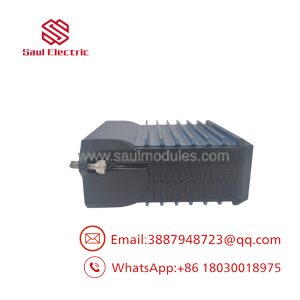
The FOXBORO FBM214b P0927AH is an eight-channel HART communication input module designed to acquire analog process signals and support digital communication with compatible smart field instruments. Each channel accepts a standard 4–20 mA signal, including a signal carrying HART Frequency Shift Keying (FSK) data.
The module is part of the Foxboro 200 Series I/O architecture. It converts analog input signals into digital values for the control system while providing a dedicated FSK modem for bidirectional communication with each HART field device. The system can request and receive HART messages for supported universal, common-practice, and device-specific commands.
Each channel has an individually isolated input circuit and loop-power supply. The module can provide isolated 24 VDC power to compatible transmitters or operate with externally powered loops. When two or more channels share a common external loop-power supply, the manufacturer specifies a Cable Balun Module to help prevent HART communication crosstalk.
Product identification
- Manufacturer: Foxboro, Schneider Electric
- Model: FBM214b
- Legacy part number: P0927AH
- Manufacturer-listed replacement part number: RH927AH
- Product type: HART communication analog input module
- Input channels: 8, individually isolated
- Analog signal range: 4–20 mA
- HART protocol support: Versions 5, 6, and 7
- System family: Foxboro I/A Series / Foxboro Evo
Key Technical Specifications
| Parameter | Manufacturer specification |
|---|---|
| Module model | FBM214b |
| Part number | P0927AH |
| Current manufacturer-listed part number | RH927AH |
| Module type | HART communication input module |
| Input channels | 8 individually isolated channels |
| Analog input | 4–20 mA |
| Digital communication | HART FSK superimposed on the analog signal |
| Supported HART versions | 5, 6, and 7 |
| HART communication | Point-to-point, master/slave, asynchronous, half-duplex |
| HART communication rate | 1,200 baud |
| HART message rate | 2 messages per second |
| Analog conversion accuracy, including nonlinearity | ±0.03% of full scale |
| Resolution | 15 bits |
| Analog update rate | 100 ms |
| Integration time | 500 ms |
| Sense resistor | 61.5 Ω nominal |
| Total input resistance | 280 Ω nominal |
| Input resistance with termination assembly, externally powered | 282 Ω |
| Input resistance with termination assembly, internally powered | 302 Ω |
| Internal transmitter loop supply | Isolated 24 VDC ±10% per channel |
| Minimum loop-supply compliance voltage | 18.5 VDC at 20.5 mA, measured at termination assembly |
| Loop supply current limit | Less than 37 mA per channel |
| Common-mode rejection | Greater than 100 dB at 50/60 Hz |
| Normal-mode rejection | Greater than 35 dB at 50/60 Hz |
| Temperature coefficient | 50 ppm/°C |
| Maximum specified field-device distance | Up to 3,030 m (10,000 ft), subject to loop conditions |
| Module power supply | Redundant 24 VDC, +5%/−10% |
| Maximum module power consumption | 7 W |
| Maximum heat dissipation | 4 W |
| Operating temperature | −20 to +70°C |
| Storage temperature | −40 to +70°C |
| Relative humidity | 5–95%, noncondensing |
| Operating altitude | −300 to +3,000 m |
| Storage altitude | −300 to +12,000 m |
| Vibration | 0.75 g from 5 to 500 Hz |
| Contamination environment | ISA S71.04 Class G3 |
| Module weight | Approximately 284 g |
| Module dimensions | 102 × 45 × 104 mm |
| Height including mounting lugs | 114 mm |
| Termination cable length | Up to 30 m |
| Baseplate-side cable connector | 37-pin D-subminiature |
| Termination-assembly-side connector | 25-pin D-subminiature |
| Calibration | Module and termination assembly calibration not required |
Technical note: The 600 VAC isolation withstand rating is a one-minute test condition. It is not an allowable continuous operating voltage for the field inputs.
Engineering Selection Highlights
Eight individually isolated analog input channels
The FBM214b accepts eight 4–20 mA analog inputs. Each channel is galvanically isolated from the other channels, ground, and module logic. This architecture is useful when multiple field transmitters must be connected to a common control system while limiting electrical interaction between input circuits.
Combined analog measurement and HART communication
The module acquires the analog current signal while supporting digital HART communication over the same loop. This allows compatible smart transmitters to provide their primary process variable through the analog signal and make supported digital information available to the control system.
The HART communication function is limited by the module’s documented message rate and supported command handling. Burst mode is not supported.
Individually isolated loop power
Each channel has an isolated internal 24 VDC loop supply, rated at ±10%, for compatible field transmitters. The current-limited design restricts each loop supply to less than 37 mA.
External loop power can also be used. If two or more channels use a common external supply, the specified Cable Balun Module is required to help maintain HART signal balance and prevent near-end crosstalk.
Sigma-delta analog conversion
The module uses sigma-delta conversion to produce updated analog input values every 100 ms. Its specified accuracy, resolution, and filtering characteristics should be evaluated against the measurement requirements of the process loop.
Redundant Fieldbus communication
The FBM214b communicates with its associated Fieldbus Communication Module (FCM) or Field Control Processor (FCP) through the redundant 2 Mbps module Fieldbus. It can communicate over path A or path B and continue over the active path if the other path fails or is switched off at the system level.
Modular installation and serviceability
The module mounts on a compatible modular baseplate. The manufacturer specifies that the module can be removed and replaced without disconnecting the field-device termination cabling, power, or communication cabling, subject to the applicable system procedures and installation design.
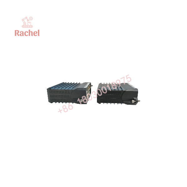
FBM214B P0927AH
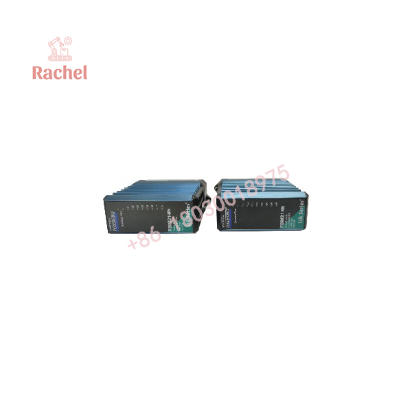
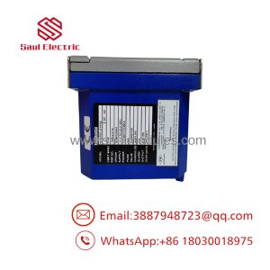
FBM214B P0927AH
System Compatibility and Integration Requirements
Control-system software
The manufacturer’s specification lists the following software requirements:
- Foxboro I/A Series software versions 8.2 through 8.8; or
- Control Core Services software version 9.0 or later.
Confirm the installed system release and hardware configuration before purchasing a replacement module.
HART field-device compatibility
The module supports HART-compliant instruments using Versions 5, 6, or 7 of the HART specification. Check the instrument’s HART version, communication settings, and required device-specific commands before commissioning.
The module supports point-to-point HART communication at 1,200 baud, with a documented rate of two messages per second. Do not select it for applications that require unsupported HART burst communication.
Field loop power
For each input, establish whether the transmitter is powered by the module’s internal loop supply or by an external source.
- Internal power: isolated 24 VDC ±10% per channel.
- External power: confirm the transmitter’s supply requirements and loop voltage budget.
- Shared external power: install the specified Cable Balun Module where multiple channels share the same external supply.
- Intrinsically safe loops: account for barrier voltage drop and the resulting reduction in permissible field-device cable distance.
The minimum loop-supply compliance voltage is specified as 18.5 VDC at 20.5 mA at the termination assembly. Confirm that the actual transmitter voltage requirement can be met after accounting for cable resistance, barriers, and other series components.
Termination assembly and cabling
The manufacturer’s specification lists the RH924JH compression-type termination assembly, superseding P0924JH, for the FBM214b. A removable termination cable connects the termination assembly to the module baseplate.
Cable options include polyurethane and low-smoke, zero-halogen (LSZH) constructions, with specified lengths up to 30 m. The baseplate end uses a 37-pin D-subminiature connector; the termination-assembly end uses a 25-pin D-subminiature connector.
For installations using shared external loop power, the specified Cable Balun Module is RH903SV, superseding P0903SV. Confirm the complete wiring arrangement in the manufacturer’s installation documentation.
Dimensions, Mounting, and Connection Notes
Module dimensions
| Mechanical parameter | Specification |
|---|---|
| Height | 102 mm |
| Height including mounting lugs | 114 mm |
| Width | 45 mm |
| Depth | 104 mm |
| Approximate module weight | 284 g |
| Mounting | Compatible modular baseplate |
| Baseplate mounting | DIN rail, horizontally or vertically; or horizontal 19-inch rack using a mounting kit |
| Alternative mounting | Supported 100 Series conversion mounting structure |
| Termination assembly mounting | DIN rail |
| Maximum termination cable length | 30 m |
The dimensions above apply to the module itself. Cabinet planning must also allow space for the baseplate, termination assembly, cable bend radius, field wiring, and maintenance access.
Field wiring
For the specified compression-type termination arrangement, the manufacturer lists these conductor sizes:
- Solid conductors: 0.2–4 mm²
- Stranded conductors: 0.2–2.5 mm²
- AWG range: 24–12 AWG
- Stranded conductors with ferrules: 0.2–2.5 mm², with or without a plastic collar
Use the applicable termination assembly’s installation instructions to determine the correct conductor preparation, tightening procedure, shielding, and grounding method.
Installation checklist
- Confirm the model and part number against the existing module.
- Verify the controller or FCM, baseplate, Fieldbus arrangement, and system software release.
- Confirm the termination assembly and cable type.
- Determine whether each transmitter uses internal or external loop power.
- Check the loop voltage budget, including cable resistance and any intrinsic-safety barrier.
- If multiple channels share a common external supply, verify the required Cable Balun Module arrangement.
- Confirm HART version and application requirements before enabling device communication.
- Perform channel-level analog and digital communication checks according to the site’s commissioning procedure.
Detailed Product Overview
How the FBM214b processes field signals
Each channel receives a 4–20 mA current signal from a compatible field instrument. The analog input circuitry converts that current into a digital value for the control system. If the field instrument also supports HART, the channel’s dedicated FSK modem communicates with the instrument through digital signals superimposed on the analog loop.
The module therefore supports two related but distinct functions:
- Analog acquisition: The current signal represents the process variable and is converted into a digital measurement.
- Digital instrument communication: HART messages support compatible universal, common-practice, and device-specific commands.
The FBM214b can request and receive two digital messages per second. This communication rate should be considered when planning device configuration, diagnostics, and control-processor loading.
Internal and external loop-power arrangements
The module provides isolated 24 VDC loop power for compatible transmitters. Where external loop power is used, the wiring design must preserve the HART communication signal’s electrical balance.
When two or more loops share a common external supply, the manufacturer specifies a Cable Balun Module to reduce HART crosstalk caused by the common power connection. Loops powered by the FBM’s internal isolated supplies do not require this balun arrangement.
Cable distance also depends on the transmitter’s required operating voltage, conductor gauge, loop resistance, and any barrier or additional series components. The stated maximum distance of 3,030 m is not a guarantee for every field installation.
Replacement-part identification
The part number P0927AH is the legacy identifier shown in the manufacturer’s specification. Schneider Electric’s document lists RH927AH as the superseding part number.
For procurement, check the installed module’s label and hardware configuration, and confirm the replacement with the supplier or applicable Foxboro documentation. Also establish whether the order includes only the FBM214b module or requires the RH924JH termination assembly, termination cable, or RH903SV Cable Balun Module.
A replacement module should not be assumed to include these separate components.
Applications and System Role
The FBM214b is suited to process instrumentation applications where a control system needs both an analog measurement and HART access to compatible field devices.
Typical applications include:
- Pressure measurement: Acquire 4–20 mA signals from compatible pressure transmitters and support HART device communication.
- Temperature monitoring: Interface with transmitters that convert temperature measurements into 4–20 mA signals.
- Flow measurement: Acquire analog flow signals and access supported digital transmitter information.
- Level measurement: Connect compatible level transmitters for process monitoring and device communication.
- Process skids: Integrate multiple smart transmitters into a Foxboro control architecture.
- Instrument diagnostics and configuration: Support HART commands used by compatible Foxboro field-device configuration tools.
The module provides the hardware interface; the control-system configuration determines how analog values, status information, alarms, and HART commands are used by the application.
Frequently Asked Questions
What is the FOXBORO FBM214B P0927AH?
It is an eight-channel HART communication input module for compatible Foxboro control systems. It accepts 4–20 mA analog signals and supports digital HART communication on compatible field-device loops.
How many input channels does the FBM214b provide?
The module provides eight individually isolated analog input channels.
Which HART versions are supported?
The manufacturer’s specification lists HART Versions 5, 6, and 7.
Does the FBM214b support HART burst mode?
No. The manufacturer’s specification explicitly excludes burst communication mode. Its documented HART message rate is two messages per second.
Can the module power field transmitters?
Yes. It provides an isolated 24 VDC ±10% loop supply for each channel, with each loop supply current-limited to less than 37 mA. Compatible externally powered loops are also supported.
Is a Cable Balun Module always required?
No. The manufacturer requires it when two or more HART loops use a common external power supply. Loops powered from the FBM’s internal isolated supplies do not require the balun.
What is the maximum field-device cable distance?
The specification states up to 3,030 m (10,000 ft) under the referenced HART physical-layer conditions. The actual permissible distance can be lower when an intrinsic-safety barrier is used or when cable resistance and voltage drop limit the transmitter’s available voltage.
Which termination assembly is specified for the FBM214b?
The manufacturer’s specification lists the RH924JH compression-type termination assembly, which supersedes P0924JH. Confirm the required cable and termination configuration for the actual installation.
What power supply does the module require?
The module’s redundant supply input is 24 VDC, +5%/−10%. The maximum specified power consumption is 7 W.
Does the module require calibration?
The manufacturer states that calibration of the module and its termination assembly is not required. Functional verification and loop checks should still follow the site’s maintenance and commissioning procedures.
Can the FBM214b be used in a hazardous location?
The manufacturer’s specification identifies applicable safety certifications for specified configurations. Certification depends on the associated processor, termination assembly, enclosure, field wiring, and installation conditions. Verify the complete system against the relevant certification documentation rather than relying on the module model alone.
What should be checked before ordering a replacement?
Verify the FBM214b identification, legacy part number P0927AH, superseding number RH927AH, system software release, baseplate compatibility, termination assembly, cable, loop-power arrangement, and HART requirements.

 Start Chat


