





Description
Product Introduction
The Foxboro 870ITEC-AYFNZ is a two-wire, loop-powered transmitter for electrodeless conductivity measurement in process applications where sensor fouling, chemical concentration, or boiler-water control must be monitored continuously. This configuration is intended for analog 4–20 mA integration rather than remote digital communication.
It accepts Foxboro 871EC and 871FT sensor families, supports selectable conductivity ranges from 50 µS/cm through 2,000 mS/cm, and can use a 100 Ω or 1,000 Ω platinum RTD or a 100 kΩ thermistor for temperature compensation.
Technical Specifications
| Parameter | Specification |
|---|---|
| Measurement principle | Electrodeless conductivity |
| Power and signal | Two-wire loop connection |
| Supply voltage | 12.5–42 VDC |
| Typical reference supply | 24 VDC |
| Output | Configurable 4–20 mA analog output |
| Digital communications | Not provided in the -A analog-only configuration |
| Conductivity ranges | 50, 100, 200, 500, 1,000, and 5,000 µS/cm; 1, 2, 5, 10, 20, 50, 100, 200, 500, 1,000, and 2,000 mS/cm |
| Measurement accuracy | Digital measurement accuracy typically ±0.3% of full scale; analog performance is based on the digital measurement accuracy plus analog output accuracy |
| Temperature inputs | 100 Ω platinum RTD, 1,000 Ω platinum RTD, or 100 kΩ thermistor |
| Temperature range | −20 to 200°C with platinum RTD; −20 to 150°C with 100 kΩ thermistor |
| Output load | Up to approximately 1,450 Ω, depending on supply voltage |
| Output damping | Selectable from 1, 5, 10, 20, 40, or 120 seconds |
| Enclosure rating | NEMA 4X and IEC IP65 |
| Mounting | DN 50 or 2-inch pipe mounting for the Y configuration |
| Sensor cable length | 30.5 m, or 100 ft, recommended maximum |
| Approximate mass | 2.8 kg, or 6.2 lb, for pipe- or surface-mounted versions |
| Hazardous-area option | FM nonincendive, suitable for Class I, II, and III Division 2 locations under the FNZ code |
The manufacturer’s specification identifies the analog output as configurable for conductivity, solution temperature, concentration, or other configured process values. The fail-output setting can be assigned between 3.8 and 20.5 mA for defined transmitter or sensor faults.
Field Application
A paper-mill boiler blowdown loop began reporting a fixed low conductivity value after maintenance replaced an aging 870ITEC transmitter. The replacement powered up, but the control room indication remained below the expected range. The fault was not the transmitter itself: the technician had selected a standard contacting-conductivity sensor profile instead of the installed 871EC electrodeless sensor type. After restoring the correct sensor selection, temperature-compensation input, cell factor, and analog scaling, the loop returned to normal operation.
The practical lesson is simple: do not treat this as a generic 4–20 mA transmitter. The sensor type, temperature element, measurement range, and output assignment must agree with the original loop configuration.
Specific applications include:
- Boiler blowdown conductivity control where the transmitter drives a modulating blowdown valve.
- Chemical concentration monitoring for caustic, hydrochloric acid, sulfuric acid, or sodium-chloride solutions.
- Steam-condensate contamination detection using a sensitive electrodeless conductivity range.
- Clean-in-place sequence monitoring with separate conductivity ranges for rinse, product, and chemical phases.
The transmitter can store up to three application configurations, including separate ranges, compensation curves, and calibration coefficients. That function is useful when a single process skid alternates between rinse water and concentrated cleaning chemicals.
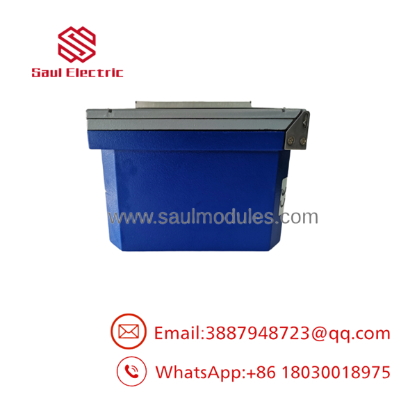
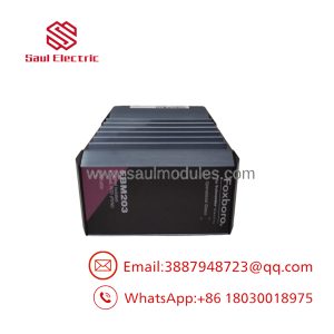
870ITEC-AYFNZ
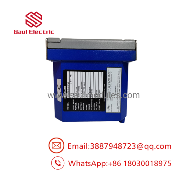
870ITEC-AYFNZ
QA and Testing SOP
For new-surplus or refurbished inventory, the following inspection sequence should be documented against the individual serial number:
- Verify the complete nameplate code, including the
-A,Y, andFNZportions and any optional suffix. - Inspect the enclosure, gasket, hinged cover, terminal block, display, keypad, mounting hardware, and cable-entry threads.
- Apply controlled 24 VDC loop power and verify startup behavior, display operation, and absence of configuration faults.
- Simulate the sensor and temperature-compensation inputs using an approved conductivity simulator or calibrated test fixture.
- Check 4 mA and 20 mA output points, intermediate scaling, output direction, damping, and configured fail signal.
- Confirm the selected RTD or thermistor input responds correctly and does not generate a temperature-compensator fault.
- Record the final configuration, calibration date, measured output values, enclosure condition, and test technician.
A seller should distinguish between “new surplus,” “used,” “refurbished,” and “repaired.” New-surplus status means the unit may be unused inventory, but it does not by itself prove current calibration, battery-free memory integrity, or field-loop compatibility. The published design stores data in EEPROM rather than battery-backed memory, but the actual condition of an aged unit still requires inspection and functional testing.
Veteran’s Tech Trap Guide
⚠️ Trap 1: Ordering by the shortened code.
870ITEC-AYFNZ describes the principal configuration, but the original purchase order may include an optional suffix. The -7 option, for example, denotes a storm door. Compare the nameplate and enclosure before approving a replacement.
⚠️ Trap 2: Treating the sensor as interchangeable.
The transmitter must be configured for the installed 871EC or 871FT sensor type and the correct cell factor. A sensor that physically connects can still produce an incorrectly scaled process value.
⚠️ Trap 3: Ignoring loop burden.
The allowable output load depends on supply voltage. At the low end of the 12.5–42 VDC range, a long cable run, barrier, isolator, and input resistor can consume too much loop voltage. Calculate the complete loop burden before installation.
⚠️ Trap 4: Misreading the hazardous-area suffix.
FNZ is a nonincendive Division 2 option, not a universal approval for every hazardous location. Verify the area classification, wiring method, barrier requirements, temperature class, and site approval documents.
PRO TIP: Record the original values for sensor type, temperature input, cell factor, engineering units, range, output direction, damping, and failure current before removing the old unit.
Dynamic FAQ
Is the 870ITEC-AYFNZ a PLC I/O module?
No. It is a Foxboro 870ITEC process transmitter. It connects to a control-system analog input or compatible Foxboro I/A Series interface and is intended for electrodeless conductivity measurement.
What output does this version provide?
The -A code identifies the 4–20 mA analog-only communication and measurement-output option. The digital IT1 and IT2 communication modes belong to the -F platform, not the analog-only version.
Which sensors are compatible?
The transmitter is designed for Foxboro 871EC and 871FT electrodeless conductivity sensors. Older compatible sensor types and certain special sensors may also be supported when the cell factor and temperature input are configured correctly.
Can it measure chemical concentration instead of conductivity?
Yes. The transmitter can be configured for concentration units such as percent by weight, grams per liter, parts per million, parts per thousand, and ounces per gallon when the appropriate compensation curve is available. User-programmable curves are also supported.
Does the unit retain configuration without a battery?
The published specification states that configuration data and calibration information are stored in EEPROM, eliminating the need for battery backup. A replacement unit should still be checked for correct configuration and calibration before being returned to service.
How should “new surplus” authenticity be verified?
Request clear photos of the original nameplate, model-code suffixes, serial number, terminal area, and enclosure. For a tested unit, obtain a functional-test record showing loop power, 4–20 mA output, sensor simulation, temperature input, and final configuration. A warranty should state whether it covers repair, replacement, return freight, calibration, and compatibility with the buyer’s specified sensor and loop configuration.

 Start Chat


