





Description
Engineering Value
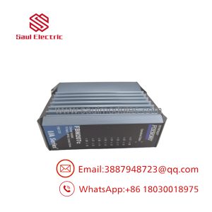
This module provides a clean interface between field transmitters and the DCS Fieldbus. Channel isolation helps prevent one damaged transmitter circuit or ground-potential problem from propagating across the input group.
The FBM201 is suited to pressure, flow, level, temperature-transmitter, and analyzer signals that use current transmission. It supports standard 4–20 mA signals while retaining a 0–20 mA input range for legacy instruments and special applications.
Technical Specifications
| Parameter | Specification |
|---|---|
| Module type | Analog input Fieldbus Module |
| Number of channels | Eight |
| Input signal | 0–20 mA DC |
| 4–20 mA compatibility | Yes, within the 0–20 mA range |
| Channel architecture | Eight isolated and independent channels |
| Analog accuracy | ±0.03% of span, including linearity |
| Accuracy temperature coefficient | ±50 ppm/°C |
| Conversion | Analog-to-digital conversion for DCS processing |
| Power input | 24 VDC, +5%/−10% |
| Maximum consumption | 7 W |
| Heat dissipation | 3 W |
| Calibration requirement | Module and termination assembly calibration is not required under the published specification |
| Communication | Redundant I/A Series Fieldbus |
| Field connection | Foxboro termination assembly |
| Operating temperature | −40 to +70°C, or −40 to +158°F |
| Relative humidity | 5–95%, noncondensing |
| Altitude | −300 to +12,000 m, or approximately −1,000 to +40,000 ft |
| Approximate dimensions | 104 mm high × 45 mm wide × 114 mm deep with mounting lugs |
| Approximate mass | 284 g, or 10 oz |
The FBM201 specification lists eight isolated channels, ±0.03% span accuracy, 24 VDC module power, 7 W maximum consumption, 3 W heat dissipation, and approximately 284 g mass.
Field Application
A water-treatment plant had eight 4–20 mA signals connected to an aging I/A Series input module: raw-water flow, discharge pressure, filter differential pressure, two tank levels, and three chemical-feed measurements. After a replacement FBM201 was installed, one flow signal remained at zero even though the transmitter loop current measured 12.6 mA at the cabinet.
The technician found a termination-assembly mismatch. The module was correct, but the field wiring had been landed on a termination assembly intended for a different analog-input variant. Once the correct termination assembly was installed and the channel database was restored, all eight values tracked the loop calibrator correctly.
Typical applications include:
- Differential-pressure transmitter inputs on filter and separator trains.
- Flow-transmitter signals from magnetic, vortex, and Coriolis meters.
- Tank-level transmitters in chemical storage and wastewater systems.
- Pressure and temperature transmitters around boiler and steam systems.
- Analyzer outputs from pH, conductivity, oxygen, and combustion-monitoring equipment.
- Compressor suction, discharge, and lube-oil pressure monitoring.
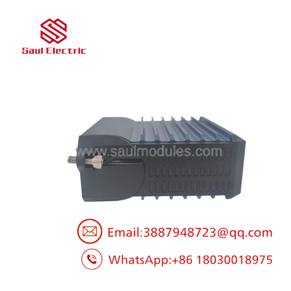
FBM201 P0914SQ
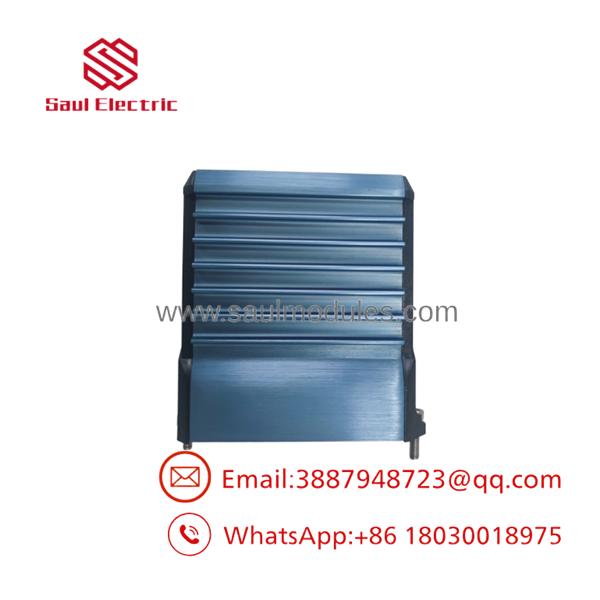
FBM201 P0914SQ
QA and Testing SOP
The official specification states that calibration of the FBM201 and termination assembly is not required, but functional verification remains important for stored or previously installed hardware.
- Record the complete module part number, revision, serial number, and termination-assembly part number.
- Inspect the housing, backplane connector, Fieldbus connectors, mounting lugs, and status indicators.
- Apply 24 VDC within the specified tolerance.
- Confirm module startup and redundant Fieldbus communication.
- Inject calibrated current at 0, 4, 12, 16, and 20 mA on each channel.
- Verify the DCS value, engineering-unit scaling, alarm state, and channel identification.
- Check all eight channels for cross-channel interaction or unexpected offsets.
- Confirm that transmitter loop power, barriers, isolators, and input wiring remain within the allowable loop burden.
- Record the measured current, reported DCS value, channel status, and test-equipment identification.
- Package the module with ESD protection and connector covers.
For new-surplus units, a power-up test alone is not sufficient. A credible test report should show current injection on all eight channels and confirmation that the Fieldbus reports each channel correctly.
Veteran’s Tech Trap Guide
⚠️ Trap 1: Ordering the wrong FBM201 variant.
FBM201 is the 0–20 mA version. FBM201b, FBM201c, and FBM201d are associated with different signal ranges, including 0–100 mV, 0–5 V, and 0–10 V. The part-number suffix matters.
⚠️ Trap 2: Assuming the termination assembly is universal.
The requires a compatible termination assembly. A module can power up and communicate while the field signals remain miswired or incorrectly referenced through an incompatible TA.
⚠️ Trap 3: Forgetting signal scaling.
A 4–20 mA transmitter may represent 0–100%, −50–150%, or another engineering range. Replacing the hardware does not automatically restore the correct DCS scaling, alarm limits, square-root extraction, or damping.
⚠️ Trap 4: Ignoring loop-power limitations.
The measures current; it does not automatically solve an underpowered transmitter loop. Include barriers, isolators, cable resistance, and transmitter minimum voltage in the loop calculation.
PRO TIP: Before removing the old module, capture each channel’s live current and DCS value. Comparing those two columns after replacement is faster than troubleshooting from the control-room display alone.
Dynamic FAQ
What signal does the P0914SQ accept?
It accepts 0–20 mA DC analog input signals. Standard 4–20 mA transmitters are therefore supported within the module’s input range.
How many channels are available?
The provides eight isolated and independent analog input channels.
Is the a voltage-input module?
No. The is the 0–20 mA current-input version. Voltage and millivolt variants use different module designations and must not be substituted without checking the I/A Series configuration.
Does the module require calibration?
The published specification states that calibration of the module and termination assembly is not required. Nevertheless, a replacement should be checked with a calibrated current source to verify channel operation, Fieldbus communication, and correct DCS scaling.
What should be verified before ordering P0914SQ?
Confirm the designation, P0914SQ part number, module revision, termination assembly, Fieldbus hardware, channel count, and input range. Also verify whether the existing installation uses redundant Fieldbus and whether any barriers or isolators are part of the signal loop.
How should new-surplus or refurbished stock be validated?
Request nameplate and serial-number photos, connector-condition photographs, and an eight-channel test report. The report should include 0, 4, 12, 16, and 20 mA test points, Fieldbus communication, channel status, and any observed input offset. The warranty should define replacement or repair coverage, return freight, testing status, and compatibility with the specified Foxboro termination assembly.

 Start Chat


