





Description
Product Introduction & Engineering Value
RH916FL is a legacy Foxboro part number that should be treated as a configuration-specific component rather than a generic industrial relay. The exact function depends on the hardware assembly and system in which it is installed.
For procurement, the safest method is to verify the complete RH916FL identification, associated Foxboro assembly or module, terminal arrangement, and electrical ratings before substitution. That matters especially when sourcing New Surplus or refurbished inventory.
Technical Specifications
| Parameter | Specification |
|---|---|
| Part Number | RH916FL |
| Manufacturer | Foxboro / Invensys |
| Product Family | Foxboro industrial control hardware |
| Hardware Category | Relay/interface component |
| Primary Function | Signal switching/interface |
| System Application | Process-control and industrial automation |
| Installation | Configuration-dependent |
| Coil/Input Rating | Verify against exact RH916FL documentation |
| Contact Rating | Verify against exact assembly documentation |
| Contact Configuration | Verify before replacement |
| Mounting/Connection | Configuration-dependent |
| Replacement Requirement | Exact part-number and electrical-rating match |
Technical caution
I would not assign a specific coil voltage, contact arrangement, current rating, or associated Foxboro module to RH916FL without a reliable manufacturer or technical-document source. The part number alone is insufficient to establish those values with confidence.
For a relay/interface spare, these are not minor details. An incorrect coil voltage or contact rating can cause immediate failure or create an unsafe control condition.
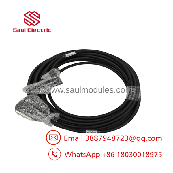
RH916FL
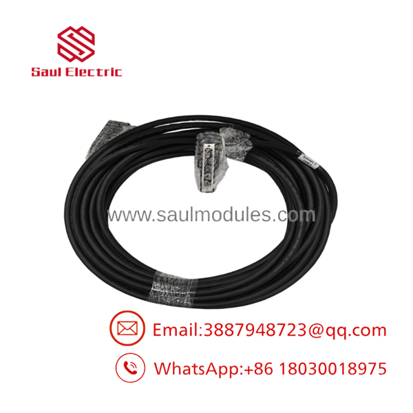
RH916FL
Field Application & the “Trench” Experience
A typical legacy-system problem starts with an output that appears correct at the control-system level but fails at the field interface. Maintenance replaces the upstream I/O component, yet the field device still does not respond.
The relay interface is then checked.
This is where RH916FL needs to be identified correctly. Before replacing it, technicians should establish whether the problem is the relay itself, its coil/input circuit, the contact circuit, the upstream I/O output, or the field load.
Niche application scenarios
- Motor starter interface: relay isolation between control-system outputs and starter circuits.
- Valve actuator command circuits: intermediate relay switching between I/O and actuator control wiring.
- Alarm/status interfaces: relay contacts used to interface process-control logic with external annunciation equipment.
Transparency SOP: QA & Testing
For New Surplus or Refurbished inventory, a meaningful inspection should include:
- Part-number verification — Confirm on the physical component or assembly label.
- Visual inspection — Look for cracked housings, damaged terminals, discoloration, corrosion, and evidence of overheating.
- Coil verification — If the exact rated coil voltage is documented, measure coil resistance and compare it with the expected value.
- Contact testing — Check normally-open/normally-closed behavior against the documented contact configuration.
- Insulation testing — Perform only with a test procedure appropriate for the actual assembly and rated components.
- Functional test — Energize the relay using the documented coil rating and verify contact switching.
- Documentation — Record the exact part number, test conditions, measured results, and warranty.
A supplier should never claim a relay has been “fully tested” without being able to identify the test conditions.
The Veteran’s Tech Trap Guide
⚠️ Trap #1 — Guessing the coil voltage
Never energize a surplus using an assumed voltage.
PRO TIP: Confirm the coil rating from the component marking, assembly drawing, or manufacturer documentation before applying power.
⚠️ Trap #2 — Checking continuity without checking load capability
A relay can show correct continuity with no load and still have damaged or degraded contacts. If the application is switching an inductive load, contact condition and suppression arrangements also matter.
⚠️ Trap #3 — Replacing the relay before checking the driving circuit
A failed output circuit can repeatedly damage a replacement relay. Check the upstream I/O output, coil wiring, suppression components, and field load before commissioning the replacement.
Dynamic FAQ
What is Foxboro ?
is a Foxboro legacy relay/interface part number used within compatible industrial control-system hardware. Its exact electrical configuration should be verified from the specific assembly documentation.
What is the coil voltage of ?
The coil voltage should not be assumed from the part number. Confirm the exact marking or technical documentation for the assembly you are purchasing.
What contact arrangement does use?
The exact contact arrangement should likewise be verified from the component or assembly documentation before replacement. Do not assume NO/NC configuration from the model number alone.
Can be replaced by a generic industrial relay?
Only after an engineering equivalency check. Coil voltage, contact configuration, contact rating, insulation requirements, mounting, terminal arrangement, and load characteristics all need to match.
How should New Surplus be verified?
Request photographs of the actual part, complete identification markings, condition information, electrical test results, and written warranty terms. For a relay, ask specifically whether coil and contact operation were tested.
Is a warranty available for ?
Warranty coverage depends on the supplier and inventory condition. For critical control-system spares, obtain the warranty period and return conditions in writing before purchase.

 Start Chat


