





Description
Product Introduction & Engineering Value
RH924UQ is a legacy Foxboro relay/interface part number. Unlike a generic panel relay, its suitability depends on the specific Foxboro assembly, wiring arrangement, and electrical requirements in which it is installed.
For a replacement, the safest approach is to verify the complete RH924UQ identification and the parent assembly before ordering. Coil voltage, contact arrangement, load rating, and terminal configuration should be confirmed from technical documentation rather than guessed from the model number.
Technical Specifications
| Parameter | Specification |
|---|---|
| Part Number | RH924UQ |
| Manufacturer | Foxboro / Invensys |
| Product Family | Foxboro industrial control hardware |
| Hardware Category | Relay/interface component |
| Primary Function | Electrical signal switching/interface |
| System Application | Industrial process control |
| Mounting | Assembly-dependent |
| Coil/Input Rating | Verify from exact component documentation |
| Contact Rating | Verify from exact documentation |
| Contact Configuration | Verify before replacement |
| Connection Arrangement | Assembly-dependent |
| Replacement Requirement | Exact electrical and mechanical match |
Engineering note
I would not assign RH924UQ a specific coil voltage, contact configuration, current rating, or switching capacity without a source specifically identifying those characteristics for RH924UQ.
For a relay component, those are functional specifications, not optional catalog details. A wrong coil rating can prevent operation; a wrong contact rating can create a premature failure or unsafe switching condition.
Field Application & the “Trench” Experience
Consider an older Foxboro cabinet where a field actuator intermittently fails to respond. The control-system output appears correct. The technician measures the relay drive and finds the command reaching the interface, but the downstream circuit remains open.
The relay becomes the prime suspect.
Before replacing RH924UQ, however, the technician should verify the coil circuit, contact operation, wiring, suppression components, and field load. A relay can fail mechanically or electrically, but the surrounding circuit can also be responsible for what initially looks like a bad relay.
Niche application scenarios
- Solenoid/actuator interface: relay contacts between control-system outputs and field actuators.
- Motor starter control: intermediate switching between Foxboro logic and starter circuitry.
- Alarm and status interface: dry-contact signaling to external annunciators or auxiliary systems.
Transparency SOP: QA & Testing
For New Surplus or Refurbished inventory, use a controlled inspection sequence:
- Part identification — Verify the actual unit is marked .
- Visual inspection — Check terminals, housing, solder joints where visible, discoloration, and corrosion.
- Coil verification — Establish the documented coil rating before applying power.
- Resistance check — Measure coil resistance where the test procedure permits.
- Contact operation — Verify the specified contact states and switching action.
- Interface test — Test using the documented coil voltage and a suitable representative circuit.
- QA record — Document test conditions, results, condition, and warranty.
A proper test report should state what was tested and at what voltage, not merely say “tested.”
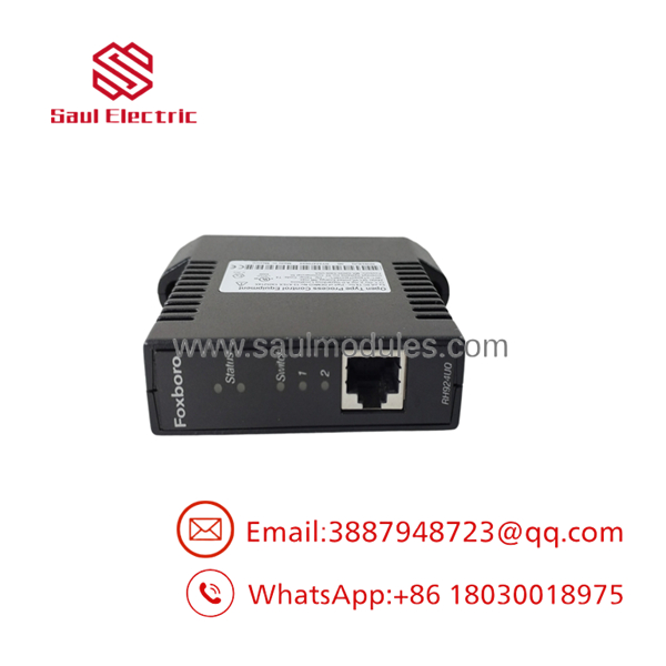
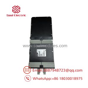
RH924UQ
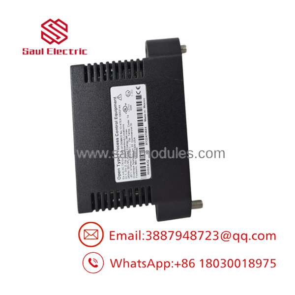
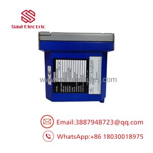
RH924UQ
The Veteran’s Tech Trap Guide
⚠️ Trap #1 — Assuming the coil is 24 VDC
Industrial control cabinets contain relays with many different coil ratings. Never apply 24 VDC to until the actual coil specification is confirmed.
PRO TIP: Photograph the relay markings before removal and retain the original unit until the replacement has been electrically verified.
⚠️ Trap #2 — Measuring coil resistance and stopping there
A resistance measurement only tells you something about the coil. It does not prove that the contacts carry the required load or that the relay performs correctly under operating conditions.
⚠️ Trap #3 — Forgetting the external load
If switches an inductive device, check the suppression network and load current. Repeated relay failures may be caused by the circuit being switched rather than by defective spare parts.
Dynamic FAQ
What is Foxboro ?
is a Foxboro legacy relay/interface part number used within compatible industrial control hardware.
What is the coil voltage?
The coil voltage should be verified from the actual component marking or applicable Foxboro documentation. It should not be inferred from the part number.
What contact arrangement does have?
The exact contact configuration needs to be confirmed against the applicable technical documentation or the original component. Do not assume NO/NC configuration.
Can be replaced with a standard industrial relay?
Only after confirming electrical and mechanical equivalence. Coil voltage, contact configuration, contact ratings, insulation, terminal arrangement, mounting, and load characteristics all need to match.
How should New Surplus be checked?
Request photographs of the actual unit, complete identification markings, condition information, coil/contact test results, and written warranty terms. For relay hardware, ask specifically whether switching operation was verified.
Does come with a warranty?
Warranty coverage depends on the supplier and inventory condition. For critical Foxboro spares, obtain the warranty period and return procedure in writing before purchase.

 Start Chat


