





Description
Product Introduction
The Fuji Electric EP-3959G-C1 is an internal gate driver and power interface board designed for high-power industrial Variable Frequency Drives (VFDs). Installed directly above the primary inverter power stage, it acts as the critical amplifier bridge between the main microprocessor control board and the high-voltage IGBT switching modules.
Engineered to withstand harsh industrial electrical environments, the EP-3959G-C1 provides isolated gate firing pulses alongside integrated desaturation protection to prevent catastrophic transistor shoot-through. Its robust circuit topology delivers precise edge transitions, minimizing thermal losses across power semiconductors during heavy acceleration and deceleration duty cycles.
Key Technical Specifications
| Parameter | Specification / Value |
| Board Type | VFD Internal Gate Drive & Power Driver Circuit Board |
| Switching Device Interface | Multi-Pack IGBT Power Modules (3-Phase Inverter Bridge) |
| Isolation Voltage | Optical Isolation (\ge 2500V RMS) Control-to-Power |
| Gate Drive Voltage | Continuous +15V On / -5V to -10V Active Off |
| Integrated Protection | IGBT Desaturation Fault Detection & Low-Side Sense |
| Onboard Voltage Sense | DC Bus Voltage Feedback Rail Interface |
| Interconnect Type | Multi-pin Ribbon Header to Control Card / Solder Pin Bus |
| Thermal Operating Range | -10^\circC to +50^\circC inside VFD chassis |
Application Scenarios & The “Trench” Experience
When a heavy-duty industrial VFD fault-trips unexpectedly with an “OC” (Overcurrent) or “LU” (Undervoltage) error code that won’t clear, the driver board is frequently the culprit. In our field experience, a shorted IGBT module almost always back-feeds high voltage into the gate firing trace, blowing out surface-mount driver transistors, zener diodes, and optocouplers on the EP-3959G-C1 board.
- Heavy Industrial Extruders – Main Drive Speed Control – Delivers precise torque regulation by maintaining sharp IGBT gate turn-on profiles under heavy load variations.
- Water Treatment Centrifugal Pumps – High-Power VFD Racks – Drives large-frame inverter sections running continuously in moist, elevated-temperature control rooms.
- Mining & Conveyor Systems – High-Inrush Material Handling – Manages high peak currents during heavy motor start-up sequences without false desaturation tripping.
Field Replacement Case: A paper recycling plant suffered an unscheduled line outage when a 150HP exhaust fan drive blew its power stage during a line voltage dip. While the technician replaced the visibly damaged IGBT module, the drive instantly blew the new transistors upon re-powering because the damaged EP-3959G-C1 gate driver card was stuck in a high-side ON state. Installing a fully bench-tested EP-3959G-C1 replacement card alongside new power modules brought the drive back online safely without risking a second bank of expensive IGBTs.
Transparency SOP: Quality Assurance & Testing
We never ship raw driver boards without testing them under real gate-charge loads:
- Inbound Component Inspection: Inspect trace pathways, solder joints, and onboard gate resistors for thermal discoloration or carbon tracking from past IGBT failures.
- Static Gate Circuit Resistance Audit: Measure resistance across all gate-emitter output channels to confirm no shorted driving transistors or open pull-down resistors exist.
- Power-On Voltage Rail Check: Energize onboard bias power regulators to verify clean, ripple-free positive and negative gate-drive voltage rails.
- Dynamic PWM Signal Simulation: Feed simulated PWM control pulses into input optocouplers while viewing output waveforms on an oscilloscope to confirm sharp rise/fall times (<200ns).
- Final Conformal Check & Anti-Static Packaging: Verify protective moisture-coating integrity before double-wrapping in static-shielding bags for safe transit.
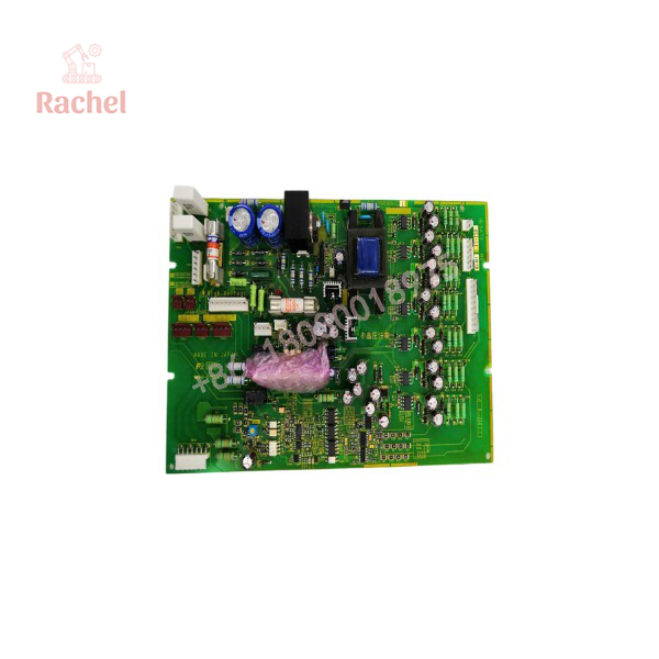
EP-3959G-C1
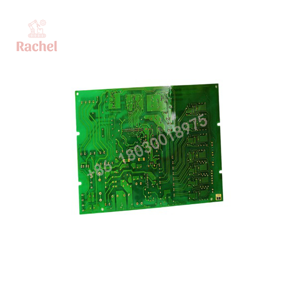
EP-3959G-C1
The Veteran’s Tech Trap Guide (Crucial Value-Add)
- ⚠️ Never Replace Just the IGBT: If an IGBT shorted out in your drive, do not install a new driver board until you have checked every gate resistor on the old card. If the old board burned out, high voltage traveled up the gate wire. Replacing the IGBT without fixing the gate driver will instantly destroy your new power module!
- ❗ Verify Sub-Revision Suffixes: Pay close attention to board sub-revisions (e.g., EP-3959G-C1 vs. EP-3959E-C3 or EP-3959D). Trace layouts, connector pinouts, or onboard current-sense resistor values often vary across drive horsepower ratings. Always match the exact board number.
- ⚠️ Check Onboard Gate Discharge Resistors: Before powering up the repaired drive, verify that all external gate connection wires between the EP-3959G-C1 and the IGBT terminals are tightly torqued. Loose gate connections cause floating gates, which destroy IGBTs within milliseconds of DC bus energization.
- ❗ Discharge DC Bus Capacitors: Wait at least 10 minutes after turning off main AC power, and verify with a multimeter that the DC bus voltage is under 5V before removing board mounting screws. High-voltage bus rails connect directly to this driver board!
Frequently Asked Questions (FAQ for Conversion)
Q: Can I substitute an EP-3959G-C1 with an EP-3959E or EP-3959C board?
A: No. While they belong to the same board family, different letter suffixes (E, D, G) and sub-revisions (C1, C2, C3) correspond to specific VFD frame sizes, voltage classes, and gate-drive current capacities.
Q: Does this board come pre-populated with gate drive optocouplers and power components?
A: Yes, the EP-3959G-C1 is a complete, fully populated printed circuit board assembly including all driver ICs, optocouplers, and passive components.
Q: Why do gate driver boards fail so often when an inverter shorts out?
A: When an IGBT collector-emitter junction breaks down, high-voltage DC bus potential (500V–800V DC) shorts directly into the gate terminal. This back-feed voltage instantly vaporizes the small driver transistors and trace lines on the gate board.
Q: Is soldering required to install this replacement card?
A: Depending on the specific Fuji drive frame size, this card either mounts via plug-in multi-pin headers with retaining screws or connects via solder pins directly to the main bus structure. Always check your drive’s internal layout before installation.
Q: How do you guarantee the reliability of surplus or refurbished gate drive boards?
A: Every surplus EP-3959G-C1 module undergoes thorough static and dynamic waveform testing on calibrated drive test fixtures to ensure all gate channels fire evenly within original OEM specifications before shipping. All parts include a full 12-month replacement warranty.

 Start Chat


