





Description
Product Introduction & Engineering Value
When an critical 5,000 HP compressor motor trips on winding overtemperature, plant engineers need far more than a simple contactor lock-out—they need immediate real-time electrical telemetry, voltage vector tracking, and embedded thermal history.
The fully specified GE Multilin 369-HI-R-M-0-E-0 solves this visibility gap by combining 12 internal RTD monitor channels with an advanced power metering package and native Modbus TCP/IP Ethernet. Its universal “HI” power supply accepts 50–300 VDC or 60–265 VAC control power, allowing maintenance teams to instantly drop this high-spec unit into existing panels to regain full motor diagnostic tracking and prevent catastrophic stator failures.
Technical Specifications
| Parameter | Specification |
| Control Power (HI) | 50 to 300 VDC / 60 to 265 VAC (45–66 Hz) |
| Thermal Monitoring (R) | 12 Built-In RTD Inputs (10Ω Cu, 100Ω Pt, 120Ω Ni, 100Ω Ni) |
| Metering Package (M) | Volts, kW, kvar, kVA, PF, Hz, MWhr + 3 Configurable Analog Outputs |
| Ethernet Interface (E) | Modbus TCP/IP Protocol via RJ45 10 Base-T / 100 Base-TX |
| Phase / Ground Current | 1 A or 5 A Secondary / Variable Ground CT Input |
| Tripping Elements | Overload (15 Standard / Custom Curves), Jam, Undercurrent, Phase Reversal |
| Serial Ports | 1 Front RS232 Port, 3 Rear RS485 Ports (Modbus RTU up to 19.2 kbps) |
| Output Contacts | 4 Form-C Assignable Relays (Trip, Alarm, Auxiliary 1, Auxiliary 2) |
| Display Panel | 40-Character LCD with LED Motor State Array (Stopped, Running, Overload) |
| Operating Temp | -20°C to +60°C (-4°F to +140°F) |
Field Application & The “Trench” Experience
A Gulf Coast gas processing plant experienced recurring nuisance trips on a 4.16 kV lean amine pump motor during high ambient summer afternoons. The original relay lacked RTD monitoring, forcing operations to run blindly without stator thermal feedback. An engineering crew retrofitted the cabinet with a 369-HI-R-M-0-E-0 relay. Using the 12 built-in RTD channels tied directly into the stator and bearing sensors, alongside real-time Modbus TCP data fed to the main DCS via the “E” Ethernet port, the control room gained complete thermal capacity used (TCU) tracking. This allowed them to optimize motor loading dynamically rather than suffering false trips.
Specific Field Applications
- Refinery Wet Gas Compressors: Tracks stator and bearing temperatures via 12 RTD channels while calculating real-time power factor (PF) and kW demand.
- Large Water Treatment High-Service Pumps: Utilizes the “M” option voltage/frequency tracking to protect against voltage unbalance and phase reversal conditions.
- Mining Sag Mill Drives: Integrates directly into plant SCADA networks over Ethernet (Modbus TCP/IP) for continuous event recording and motor health logging.
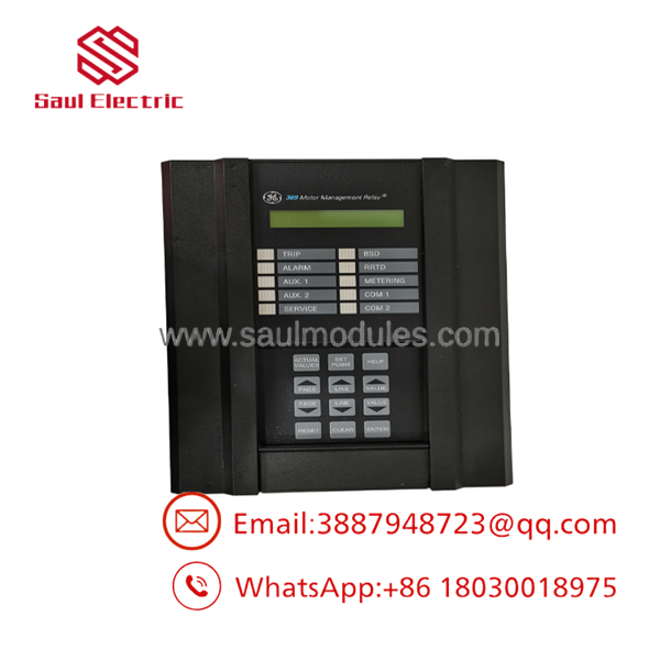
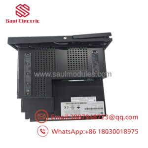
- 369-HI-R-M-0-E-0
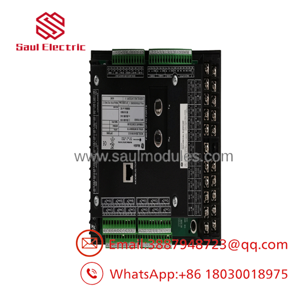
- 369-HI-R-M-0-E-0
Transparency SOP: QA & Testing
- Power Supply & Universal Input Check: Bench testing the “HI” power card across the full voltage spectrum (50 VDC up to 265 VAC) to ensure power supply regulation stability.
- 12-Channel RTD Calibration: Connecting decade resistance boxes across all 12 RTD terminal pairs to verify measurement accuracy within ±1°C for Pt100, Ni120, and Cu10 sensors.
- Metering & Voltage Injection: Applying three-phase voltage and current signals via a secondary injection test set to verify V, A, kW, kVA, and power factor readout accuracy.
- Ethernet & Serial Communication Stress Test: Ping testing and setpoint read/write verification over the RJ45 Modbus TCP Ethernet port (“E” option) and all RS485 serial channels.
- Output Relay Contact Load Testing: Cycle testing all 4 Form-C output relays under electrical load to confirm contact resistance meets factory tolerances.
The Veteran’s Tech Trap Guide
⚠️ RTD Shield Grounding Loop: When wiring the 12 RTD inputs on the “R” option, ground the cable shields at the 369 relay end only. Grounding RTD shields at both the motor terminal box and the relay creates ground loops that introduce electrical noise into sensitive temperature readings.
PRO TIP: If you are replacing a standard 369 relay with this feature-packed 369-HI-R-M-0-E-0 unit, remember that enabling the “M” (Metering) option requires external PT (Potential Transformer) connections to terminals B1 through B6. Without PT inputs wired, the relay will generate a persistent “Phase Voltage Low” alarm.
⚠️ Ethernet IP Address Assignment: Unlike basic serial Modbus RTU units, the “E” option Ethernet interface requires a static IP address setpoint. Always verify and configure the relay’s IP, subnet, and gateway settings via the front panel keypad before connecting it to a live plant network to prevent IP conflict shut-downs.
Dynamic FAQ
Q: What do the specific code suffix letters “R”, “M”, and “E” mean on this 369 relay?
A: R indicates 12 built-in RTD temperature inputs; M includes the complete power metering package (voltage, power, power factor, plus 3 additional analog outputs); E adds an embedded Ethernet port supporting Modbus TCP/IP communications.
Q: Can I use this relay on a motor powered by a 24 VDC control bus?
A: No. The “HI” designation requires 50–300 VDC or 60–265 VAC. If your station control voltage is 24 VDC or 48 VDC, you must order the “LO” power supply variation (369-LO-…).
Q: Do I need extra hardware to use the EnerVista 369 software with the “E” option?
A: No. You can connect directly to the relay using standard Cat5e/Cat6 patch cables via the front RS232 port or over your local network using the rear Ethernet RJ45 port.
Q: Does this unit ship fully tested with a warranty?
A: Yes. All New Surplus and factory-refurbished 369-HI-R-M-0-E-0 units undergo a complete 5-stage bench test and are backed by a standard 1-year functional replacement warranty.


 Start Chat


