





Description
Product Introduction & Engineering Value
Upgrading or replacing a protective relay on a critical 13.8 kV motor drive can derail a planned turnaround if the current transformer ratios or analog interfaces do not line up. Installing a standard 5A CT relay into a cabinet wired for 1A secondary CTs causes severe current sensing errors, leaving your high-horsepower motor completely unprotected.
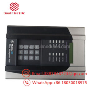
The GE Multilin 469-P1-HI-A20-T eliminates those integration headaches. Designed specifically for installations with 1A phase CT secondaries, this module pairs a high-range universal power supply (HI) with four isolated 4–20 mA analog outputs (A20) and a dedicated 10BaseT Ethernet port (T). It delivers sub-cycle thermal overload protection while piping real-time motor telemetry directly into plant DCS and SCADA networks via Modbus TCP/IP.
Technical Specifications
| Parameter | Specification |
| Phase CT Inputs (P1) | 1 A Secondary Nominal (CT Burden < 0.2 VA at 1 A) |
| Control Power (HI) | 50 to 300 VDC / 60 to 265 VAC (45–66 Hz) |
| Analog Outputs (A20) | 4 Isolated 4–20 mA Outputs (Fully Assignable, Max Load 1200 Ω) |
| Ethernet Interface (T) | Rear 10BaseT RJ45 Port (Modbus TCP/IP Protocol) |
| Ground CT Options | 1 A / 5 A Secondary or 50:0.025 Sensitive Ground Input |
| RTD Inputs | 12 Onboard Channels (Supports 10Ω Cu, 100Ω Pt, 120Ω Ni, 100Ω Ni) |
| Trip/Alarm Contacts | 6 Assignable Form-C Output Relays (Trip, Alarm, Auxiliary 1–3, Block Start) |
| Metering Capabilities | True RMS Current, Voltage, Power (kW, kVA, kvar), PF, Frequency, Event Logs |
| Front Interface | 40-Character LCD Display with Full Keypad and RS232 Port |
| Operating Temperature | -20°C to +60°C (-4°F to +140°F) |
Field Application & The “Trench” Experience
A pulp and paper mill in the Pacific Northwest experienced nuisance trips on a 3,500 HP refiner motor following a DCS modernization. The legacy relay lacked high-speed network support and couldn’t pass 4–20 mA process trends (like thermal capacity used) to the main operator graphics. The maintenance team retrofitted the cabinet with a GE 469-P1-HI-A20-T unit. Using the P1 terminals to match the existing 1A CT setup and tying the A20 analog outputs to local chart recorders, they simultaneously established a Modbus TCP/IP link over the T Ethernet port—giving operators complete real-time motor thermal tracking and eliminating unnecessary trip shutdowns.
Specific Field Applications
- Refiner and Chipper Drives: Protects heavy high-inertia induction motors using adaptive thermal modeling and stator RTD temperature tracking.
- Petrochemical Boiler Feed Pumps: Uses the A20 4–20 mA outputs to feed real-time motor current and power factor data directly into local PLC control loops.
- Mining Sag and Ball Mills: Connects directly into plant Ethernet backbones via the T option port to log fault waveform captures and event histories.
Transparency SOP: QA & Testing
- Power Supply Validation: Bench testing the “HI” power supply card across the complete operating envelope (50 VDC up to 265 VAC) to ensure internal voltage regulation stability.
- Current Injection & Calibration: Injecting precise 1A secondary signals via a three-phase secondary injection test set to verify CT input accuracy and trip timing curves.
- Analog Output Sweep (A20): Measuring output current across all four 4–20 mA terminals with a calibrated digital multimeter at 0%, 50%, and 100% full-scale setpoints.
- Ethernet Communication Stress Test: Continuous ping testing, packet loss analysis, and setpoint read/write verification over the rear RJ45 Ethernet port (T option).
- Full Thermal Burn-In: 24-hour continuous operational test inside a climate chamber at 50°C to catch potential component thermal drift before final packaging.
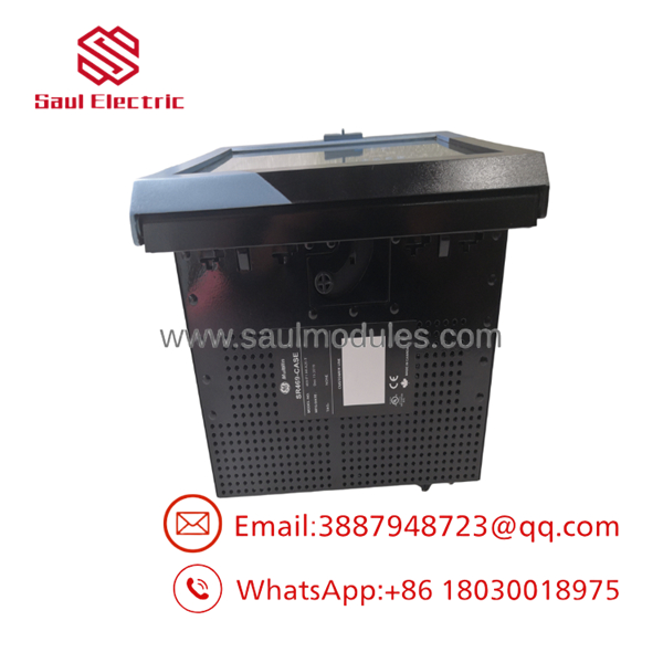
- 469-P1-HI-A20-T
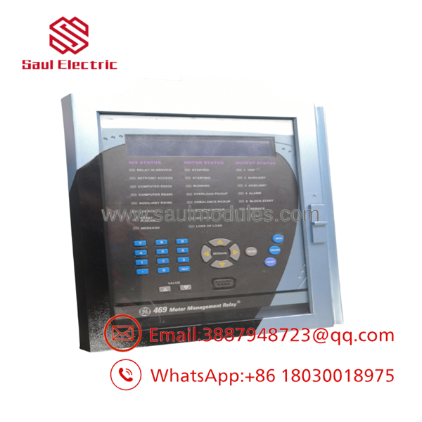
- 469-P1-HI-A20-T
The Veteran’s Tech Trap Guide
⚠️ CT Secondary Rating Mismatch: Double-check your current transformer secondary ratings before powering up! The “P1” suffix means this unit requires a 1 Amp secondary CT. Connecting a standard 5 Amp CT circuit to a P1 module will saturate the internal input transformers, destroy accuracy, and potentially cause a flashover fault.
PRO TIP: When upgrading an older serial-only 469 relay to this Ethernet-enabled “T” model, remember that the Ethernet option uses a dedicated static IP address. Before inserting the relay into a live panel, connect via the front RS232 port using EnerVista software to set the IP, Subnet, and Gateway parameters.
⚠️ Drawout Case Terminal Interlocks: Always verify that the drawout case shorting bars are fully engaged before racking out the relay module. If a shorting bar is bent or loose, racking out the unit will open the live CT secondary, creating a high-voltage hazard across the rear terminal block.
Dynamic FAQ
Q: What is the main difference between a 469-P1 and a 469-P5 relay model?
A: P1 specifies 1 Amp phase current transformer inputs, while P5 specifies 5 Amp phase CT inputs. You must select the model that matches your physical CT secondary wiring.
Q: What does the “T” option designation mean on this 469 relay?
A: The T option indicates a rear 10BaseT Ethernet port supporting Modbus TCP/IP protocol, enabling fast network communications with plant SCADA or DCS systems.
Q: Can I use the 4-20 mA analog outputs (A20 option) to drive external meters?
A: Yes. The four A20 outputs are fully isolated and assignable to parameter values like phase current, thermal capacity used, motor power (kW), or RTD temperatures, driving loads up to 1200 ohms.
Q: Does this unit ship with test reports and warranty coverage?
A: Yes. Every New Surplus and fully reconditioned 469-P1-HI-A20-T relay includes a complete 5-stage bench test report and is backed by a standard 1-year functional replacement warranty.


 Start Chat


