





Description
Key Technical Specifications
| Parameter | Value / Specification |
|---|---|
| System Compatibility | GE Speedtronic Mark V / Mark VI Control Systems |
| Catalog Base Number | V7668A-1310B0 |
| Manufacturing Tracking Code | 350-9310007668-131020 |
| Hardware Revision Level | Revision D |
| Form Factor | 6U Single-Slot VME physical footprint |
| Data Bus Framework | Standard 16-bit / 32-bit VMEbus backplane interface |
| Onboard Connectivity | Multi-port high-speed serial data paths, specialized diagnostic breakout ports |
| Power Consumption | Powered via the +5 VDC and +12 VDC VME backplane rails |
| Component Guarding | Complete heavy-duty industrial conformal coating against airborne contamination |
| Thermal Operating Window | 0 to 65°C (32 to 149°F) continuous cabinet environment |
Product Introduction
The GE V7668A-1310B0, carrying the technical factory manufacturing code 350-9310007668-131020, is a single-slot 6U VME communication interface and data serialization processor built for the GE Speedtronic Mark V and Mark VI turbine control platforms. This board functions as a high-speed data hub within the main control rack cage, orchestrating critical real-time information exchange between the localized logic processors and external unit data networks. It plays an essential role in keeping control parameters synchronized across heavy-duty gas and steam turbine systems.
Engineered under structural Revision D specifications, this board features a robust multi-layer PCB layout populated with dense communication arrays designed to handle heavy data throughput without processing delays. By offloading complex network processing and data packaging tasks from the main turbine application cores, the V7668A-1310B0 preserves the primary processors’ execution bandwidth. This architecture guarantees sub-millisecond predictability for vital safety and machine-trip protective algorithms.
Installation & Configuration Guide
Stage 1: Pre-Installation Preparation (Estimated Time: 15 minutes)
- ⚠️ Safety First: The V7668A-1310B0 interface board manages real-time telemetry pathways that influence valve tracking and system diagnostics. Never remove or insert this card while the host VME backplane is powered. Bring the turbine process to a verified standstill, isolate field controllers, and execute a full lock out/tag out (LOTO) on the core control power supply breaker feeding the VME card cage.
- Tools Required: Grounded anti-static prevention wrist strap, medium flathead screwdriver, laptop running the corresponding version of your system’s GE software suite (Toolbox or related HMI diagnostic utility).
- Data Backup: Connect your engineering laptop to the panel before killing power. Extract and back up all active communication register structures, data routing tables, and node network definitions assigned to this physical card slot position.
Stage 2: Removing the Old Module (Estimated Time: 5 minutes)
- Affix your ESD prevention wrist strap to a bare metal chassis structural beam inside the control cabinet frame.
- Label each network line, serial communication cable, and auxiliary connector attached to the board faceplate to prevent cross-wiring during reassembly. Unplug the lines gently.
- Loosen the upper and lower faceplate retaining screws using your flathead screwdriver.
- Grasp the top and bottom injector/ejector tabs on the module faceplate. Press them outward simultaneously to unseat the card from the high-density internal VMEbus rear pin slots.
- Slide the card smoothly straight out of its guide rails. Place the assembly directly into an ESD protective shielding bag.
Stage 3: Installing the New Module (Estimated Time: 10 minutes)
- Unpack the new V7668A-1310B0 Revision D module from its static-safe package, keeping your fingers away from the rear connector pins.
- ⚠️ Visual Inspection: Look down the rear edge connector array to verify that all VME backplane connector pins are perfectly straight, parallel, and free of dust or manufacturing debris.
- Align the circuit board edges with the designated single-slot rack guide tracks. Slide the module smoothly into the card cage until the faceplate ejector tabs touch the frame rails.
- Press both ejector handles inward firmly until they snap flat against the faceplate, locking the card securely into the rear backplane socket.
- Tighten the top and bottom retaining screws to anchor the module against structural vibrations, and reattach the labeled communication lines to their matching ports.
Stage 4: Power-On & Commissioning (Estimated Time: 20 minutes)
- Re-energize the primary VME control rack power supply breaker.
- Monitor the diagnostic status indicators on the module faceplate during its initial power-up boot sequence:
- The primary power lights should stabilize into a steady green display.
- Communication indicators on active ports should show high-frequency flashing data traffic.
- ⚠️ Troubleshooting: If a solid amber or red hardware fault indicator remains lit after 3 minutes, check the workstation software error logs for an electronic ID signature conflict or a localized node mismatch.
- Establish a data connection via your engineering workstation software. Match the physical board revision with your project file mapping, and download your archived routing table and network parameters to restore full system communication.
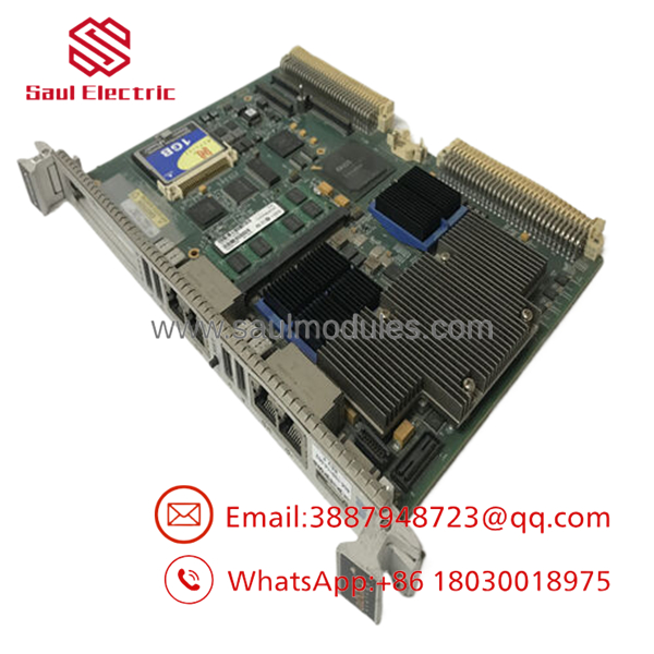
- V7668A-1310B0 350-9310007668-131020 D
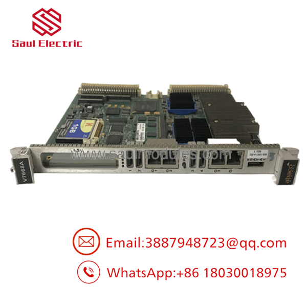
- 350-9310007668-131020 D
Frequently Asked Questions (FAQ)
Can I hot-swap the while the turbine is running online?
No. You must never hot-swap this card. The handles critical data serialization across the interior VME data bus. Pulling the module while the backplane is live interrupts real-time data paths, which will drop important tracking metrics and instantly trip the turbine system. Always completely isolate the rack power supply before extracting the module.
What is the relationship between code and number 350-9310007668-131020?
The alphanumeric string is General Electric’s catalog identification and ordering model code, which defines the general board series, functional footprint, and baseline configuration parameters. The numeric string 350-9310007668-131020 is the technical hardware manufacturing part number and factory assembly reference used during production tracking. Both codes must match to guarantee exact hardware component alignment.
Does this interface module require its own independent firmware flash after a swap?
The relies on hardware configuration parameters sent down from the rack’s master controller module during system startup. While it does not run its own independent operating system, you should always verify through your engineering workstation that the newly installed board’s hardware revision (Revision D) is correctly recognized by your software project configuration tree to prevent communication errors.
Why do some versions of this board have different letter revisions at the end?
The trailing letter (such as the “D” flagged on this module) indicates the factory hardware revision level. GE continuously updated these legacy boards over their production lifecycles to introduce improved trace insulation, higher component tolerances, or more robust electronic filtering components. Revision D components are typically backward-compatible with older revisions, provided your configuration software recognizes the hardware signature.
Why are these legacy VME modules sold as “New Surplus” stock?
Since GE transitioned support for the legacy Speedtronic Mark V and Mark VI control systems to newer turbine management networks, these specific VME card variations are no longer in active production. Our stock consists of New Original / New Surplus units—unused factory spares preserved from plant cancelations, distribution liquidations, or warehouse overstock. This provides an authentic replacement part without long factory production lead times.


 Start Chat


