





Description
Product Introduction & Engineering Value
The DS200GSIAG1B belongs to the drive-side electronics of GE’s legacy Mark V platform. Its role is tied to common DC-bus regeneration, making it part of the power-conversion and drive-control chain rather than a conventional turbine sequence or analog I/O board.
This distinction matters when sourcing a replacement. The GSIA family contains multiple revisions and configurations, including DS200GSIAG1, DS200GSIAG1A, DS200GSIAG1B, and DS200GSIAG1C. The complete part number should be matched rather than ordering by the generic “GSI” designation.
Technical Specifications
| Parameter | Specification |
|---|---|
| Manufacturer | General Electric |
| Part Number | DS200GSIAG1B |
| Series | Mark V DS200 |
| Functional Acronym | GSIA |
| Functional Description | Common DC Bus Regenerative Board |
| Functional Revision | B |
| PCB Coating | Normal coating |
| Mounting | VME rack |
| 40-Pin Connectors | 3 |
| 16-Pin Connectors | 2 |
| 8-Pin Connector | 1 |
| Jumpers | 6 |
| Test Points | Multiple |
| Status LED | 1 side-visible LED |
The board is documented with three 40-pin connectors, two 16-pin connectors, one 8-pin connector, six jumpers, and multiple test points. It also has a side-visible LED that indicates board activity.
Diagnostic detail
The onboard LED is visible with the cabinet door open. According to the available technical reference, a lit or flashing LED indicates processing activity, while an unlit LED warrants further troubleshooting. The Mark V drive’s diagnostic functions can also generate component information for troubleshooting the board.
Specification caution: Public references establish the DS200GSIAG1B’s board function and hardware configuration, but they do not provide enough authoritative information to state exact DC-bus voltage, regenerative current, switching frequency, or thermal ratings. Those values should come from the applicable GE drive documentation.
Field Application & the “Trench” Experience
A legacy turbine drive begins reporting a regeneration-related fault during deceleration. The drive still starts normally, so the first assumption is that the problem is in the braking or load circuit.
The maintenance team checks the DC bus, associated power components, cabling, and drive diagnostics before condemning the DS200GSIAG1B. When the board is removed, the replacement is compared connector-for-connector and jumper-for-jumper. The six jumper positions are documented before installation.
That last step is easy to skip. It should not be. On an obsolete Mark V drive board, a physically similar PCB with a different configuration can create a second fault after the original one has been repaired.
Specific application scenarios:
- Common DC-bus regenerative drive systems
- GE Mark V turbine auxiliary drives
- Regenerative braking during turbine-drive deceleration
- Legacy AC/DC drive cabinet maintenance
- Mark V drive obsolescence and spare-parts replacement
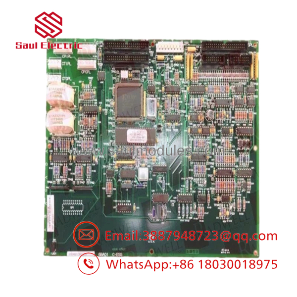
DS200GSIAG1B
Transparency SOP: QA & Testing
For DS200GSIAG1B, QA should focus on the power-interface hardware and configuration.
1. Identification
Verify the complete part number and functional revision B.
2. Physical inspection
Inspect all six connector groups, jumper headers, test points, PCB traces, solder joints, capacitors, resistors, transistors, and integrated circuits.
3. Jumper verification
Record all six jumper positions and compare them with the customer’s original board or approved GE configuration.
4. Connector inspection
Check the three 40-pin connectors, two 16-pin connectors, and 8-pin connector for bent contacts, oxidation, cracked housings, and mechanical damage.
5. Functional testing
Use an appropriate Mark V/drive test procedure to verify the board’s regenerative interface and logic functions. A basic continuity test is not sufficient for a power-conversion control board.
6. LED/diagnostic verification
Confirm the board’s activity indication and, where available, verify the associated drive diagnostic reporting.
7. Final QA
Record actual-unit photographs, jumper configuration, test results, condition, and warranty status.
For New Surplus, confirm that the board is unused and determine whether it has ever been energized. For Refurbished, request the repair scope and functional-test documentation.
The Veteran’s Tech Trap Guide
⚠️ Trap #1 — Don’t confuse a common-bus board with a generic I/O card.
The DS200GSIAG1B is part of the drive/regeneration architecture. Its failure symptoms can involve DC-bus or regeneration behavior rather than conventional turbine I/O.
⚠️ Trap #2 — Photograph the jumpers.
The board has six jumpers. Record their original positions before removal. A replacement with a different jumper configuration should not be installed blindly.
⚠️ Trap #3 — An inactive LED is a clue, not a diagnosis.
The side-mounted LED provides useful activity information, but an unlit LED does not by itself identify the failed component. Check the drive’s diagnostic information and surrounding circuitry.
PRO TIP: Keep the board photograph, jumper map, and Mark V drive diagnostic report together in the maintenance record. That combination is far more useful during a repeat failure than the PCB part number alone.
Dynamic FAQ
Q: What is the GE DS200GSIAG1B?
A: It is a GE Mark V Common DC Bus Regenerative Board, with the functional acronym GSIA.
Q: What systems use the DS200GSIAG1B?
A: It is associated with GE Mark V automated drive assemblies used in wind, steam, and gas turbine applications.
Q: How many connectors does the board have?
A: The documented configuration includes three 40-pin connectors, two 16-pin connectors, and one 8-pin connector.
Q: Does DS200GSIAG1B have onboard diagnostics?
A: It has a side-visible activity LED and multiple test points. The associated Mark V drive also provides diagnostic functions that can report information about installed components.
Q: Can another DS200GSIAG1 revision replace DS200GSIAG1B?
A: Do not assume interchangeability. The Mark V catalog identifies multiple GSI configurations and revisions. Verify the complete part number, revision, jumper configuration, and drive application before substitution.
Q: How should New Surplus authenticity and Refurbished quality be verified?
A: For New Surplus, request actual-unit photographs and confirmation that the board has never been installed or energized. For Refurbished units, request the repair scope, jumper/configuration verification, functional-test results, serial traceability, and written warranty/DOA terms. Current secondary-market listings identify DS200GSIAG1B in both surplus-new and refurbished conditions, so the material classification should be confirmed in writing.


 Start Chat


