





Description
Key Technical Specifications
| Parameter | Value |
| Processor Type | Intel Core 2 Duo T7400 |
| Processor Clock Speed | 2.16 GHz |
| L2 On-Die Cache | 4 MB shared |
| System Memory | 1 GB DDR2 SDRAM running on a 667 MHz bus |
| Chipset | Intel 945GME Express Chipset |
| Bus Interface | 6U VMEbus architecture with Tundra Universe II VME64 bridge chip |
| Front Panel Layout | 1101.10 compliant layout containing video, dual Ethernet, USB, and serial ports |
| Network Channels | 2 x 10/100/1000Base-T Gigabit Ethernet interfaces |
| Local Storage Expansion | 1 x Onboard bootable CompactFlash site (supports up to 8 GB flash) |
| Local Device Interfaces | 4 x USB 2.0 ports, 2 x SATA connections, 2 x COM ports (RS-232/422/485) |
| Hardware Expansion Mezzanine | 1 x PCI-X PMC site featuring the EasyRail mounting mechanism |
| Operating Temperature | 0 to +55 °C (32 to 131 °F) for standard commercial airflow profiles |
Product Introduction
The GE V7768-320001 (board number 350-9301007768-320001 C) is a high-reliability 6U VMEbus Single Board Computer designed by GE Fanuc Intelligent Platforms (now Abaco Systems) for demanding industrial processing, power generation control, and complex data acquisition. Powered by an Intel Core 2 Duo 2.16 GHz processor, this main CPU module delivers deterministic computing performance for computing-heavy industrial loops and legacy gas/steam turbine system controllers.
Equipped with a solid Tundra Universe II VME64 bridge, the V7768-320001 provides a seamless upgrade path for aging VME architectures without requiring re-engineering of the existing backplane setup. Its hardware design incorporates rich onboard communication channels—including dual Gigabit Ethernet lines and an integrated PCI-X PMC expansion site—allowing facility maintenance teams to maintain operational stability in rugged, high-vibration power plant and mill environments.
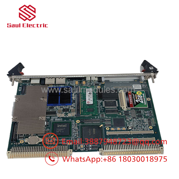
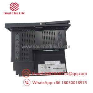
- V7768-320001 350-9301007768-320001
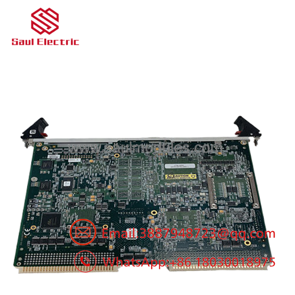
- V7768-320001 350-9301007768-320001
Installation & Configuration Guide
Stage 1: Pre-Installation Preparation (Estimated Time: 15 minutes)
- ⚠️ Safety First: Confirm that the target VME subrack chassis is completely powered down. Never hot-swap or insert this CPU while the backplane rails carry active voltages, as doing so will blow out the Tundra Universe interface chip or corrupt system partition tables.
- Tools Required: Grounded static-dissipative wrist strap, clean anti-static work surface mat, and a fine flathead tool for extraction clip adjustments.
- Data Backup: Ensure that all running runtime partitions, boot sequence attributes, and local application logic binaries are backed up from your host engineering station.
Stage 2: Removing the Old Board (Estimated Time: 5 minutes)
- Affix your ESD wrist strap to a verified frame ground terminal on the enclosure rack.
- Disconnect all front-panel peripheral connections, including Ethernet channels, serial terminal links, and USB devices.
- Loosen the upper and lower faceplate retaining thumb fasteners.
- Unlock the dual 1101.10 injection/ejection handles by squeezing the clips and pivoting them outward to release the pins from the rack lips.
- ⚠️ Note: Pull the board smoothly straight out of the slot along the plastic card guides. Avoid flexing the multilayer PCB or touching any components on the solder sides. Slide the card directly into a protective static-shielding bag.
Stage 3: Installing the New Board (Estimated Time: 15 minutes)
- Unpack the replacement V7768-320001 card on your grounded static-dissipative mat.
- Configuration Clone: Check the layout configuration of the CompactFlash card on the old board. Carefully move the bootable CompactFlash storage card over to the replacement board’s slot, or ensure the replacement flash contains identical master software images. Verify any local custom onboard jumpers match.
- Open the top and bottom extraction handles on the new card fully outward.
- Guide the card evenly into the designated VME slot track, sliding it rearward until the edge connectors meet the backplane receptacle pins.
- Push the front panel handles inward firmly; the pivoting action will smoothly engage the connector arrays into place.
Stage 4: Power-On & Testing (Estimated Time: 15 minutes)
- Re-attach the primary serial terminal monitor and network cables to the corresponding front panel interfaces.
- Apply input power to the main VME chassis.
- Watch the local LED startup progression. The board’s status lights will execute a POST routine, transitioning out of reset into a green RUN/OK state as the operating system kernel initiates from flash storage.
- Access the boot-loader or BIOS settings via terminal console to confirm system clocks, RAM detection (1 GB), and memory map configurations conform to site standards.
- ⚠️ Troubleshooting Note: If the board drops into a continuous boot loop or shows no serial display output, check for bent backplane pins in the VME rack slot, or verify that the flash card’s file formatting matches the exact operational revision requirements of your local system.
Frequently Asked Questions (FAQ)
What operating systems are natively compatible with this V7768 SBC hardware?
The platform is built to support industrial and embedded operating systems, including VxWorks (via Board Support Packages for Tornado/Workbench), Windows Embedded, and industrial Linux distributions. The matching OS layer depends entirely on the compiled boot file image installed on your local CompactFlash storage card.
Can I run a -320001 card in an older VME64 or standard VME chassis slot?
Yes, because the card relies on the Tundra Universe II VME64 bridge chip, which provides comprehensive backward compatibility with legacy VMEbus backplanes. It fits standard 6U form factor chassis configurations, provided that the physical slot pitch aligns with standard 1101.10 front-panel depth specs and airflow properties match the layout requirement.
What does the “350-9301007768-320001 C” part number variation signify?
The number string 350-9301007768-320001 C is the specific PCB assembly and manufacturing fabrication part number assigned directly by the GE Fanuc factory lines. The “C” designator tracks the structural hardware board revision level. System integrators match this specific trace number to guarantee absolute component compatibility for replacement setups in safety-critical loops.
Will the replacement card preserve my network configuration properties automatically?
No, because core IP designations, node configurations, and application variables are loaded during boot runtime from the OS layer. If you migrate your old CompactFlash card to the new board, these attributes should load normally. If you use a fresh flash drive, you must manually run configuration scripts via terminal serial port utility to restore system parameters.
What is the exact condition of this stock since it is a discontinued model?
Our available inventory comprises New Original (New Surplus) units stored in pristine condition within our ESD-compliant warehouse facility. Since Abaco/GE Fanuc ceased active mass assembly lines for this generation, components are tested using diagnostic test rigs to verify full RAM verification, peripheral interface function, and stable VME bus signaling before dispatch.


 Start Chat


