





Description
Product Introduction
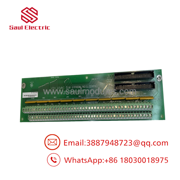
The GE DS200TBCAG1AAB functions as an Analog I/O Terminal Board (TBCA) within the legacy GE Speedtronic Mark V turbine control system. Located inside the terminal cabinet of Mark V control enclosures, the TBCA board serves as the critical field connection point for incoming analog telemetry—including resistance temperature detectors (RTDs), 4-20 mA process loops, and 0-10 V feedback signals.
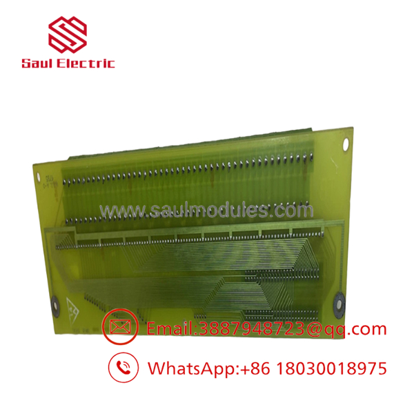
Featuring two large barrier terminal strips housing 180 individual screw connections alongside two 50-pin ribbon connectors (JCC and JDD), the DS200TBCAG1AAB board channels field instrumentation signals directly to internal processor boards (such as the TCCA core card). Its robust design protects upstream digital processing cards from external electrical transients while maintaining low-resistance signal paths.
Key Technical Specifications
| Parameter | Specification |
| Manufacturer | General Electric (GE) |
| Part Number | DS200TBCAG1AAB |
| System Line | Speedtronic Mark V Turbine Control |
| Functional Acronym | TBCA (Analog I/O Terminal Board) |
| Revision Level | Group 1 (G1) | Artwork B | Functional Rev AA |
| Terminal Count | 2 Terminal Blocks with 90 screw terminals each (180 Total) |
| Ribbon Connectors | 50-pin JCC Connector & 50-pin JDD Connector |
| Signal Compatibility | RTD inputs (1-30 channels), 4-20mA transmitter loops, voltage signals |
| Primary Core Linking | Connects to TCCA card in R5 Core |
Application Scenarios & The “Trench” Experience
During steady-state operation of a heavy-duty gas turbine, operators observe fluctuating RTD temperature readings on the Mark V HMI screen, accompanied by intermittent analog input open-circuit diagnostic alarms. Field inspection reveals trace oxidation and thermal damage on terminal points on an aging TBCA card. Maintenance engineers perform a planned tag-out, unseat external field wiring and the two 50-pin cables, and install a bench-tested DS200TBCAG1AAB replacement. Once all 180 field wires are re-landed and the JCC/JDD ribbon connectors are latched, signal stability is completely restored to the TCCA processor.
- Gas & Steam Turbine Controls – Sensor Termination – Direct landing point for turbine bearing RTDs, oil pressure transmitters, and valve position feedback loops.
- Control Cabinet Overhauls – Hardware Refresh – Direct replacement for degraded terminal strips without requiring rewiring of system-side backplanes.
- RTD Telemetry Processing – Multiplex Routing – Routes RTD channels 1-15 via JCC and 16-30 via JDD connectors directly to the R5 core processor.
Transparency SOP: Quality Assurance & Testing
- Visual & Mechanical Audit: High-magnification inspection of all 180 screw terminal posts, verifying thread integrity, absence of trace corrosion, and structural PCB health.
- Connector & Pin Inspection: Micro-polishing the pins on 50-pin connectors
JCCandJDDto ensure zero contact resistance across backplane cables. - Trace Continuity & Isolation Check: Multi-point resistance testing across terminal rails to rule out micro-fractures, short circuits, or ground faults.
- Pass-Through Signal Integrity Test: Injecting calibrated reference current and voltage signals across terminal points to verify clear signal routing through the ribbon headers.
- Anti-Static ESD Packaging: Enclosed in heavy-duty static-shielding ESD bags with fresh desiccant packages prior to protective shipping encapsulation.
DS200TBCAG1AAB
DS200TBCAG1AAB
The Veteran’s Tech Trap Guide (Crucial Value-Add)
- ⚠️ LABEL FIELD WIRES BEFORE REMOVAL: With 180 terminal screw positions, mislanding even a single wire can cause improper analog readings or trip a channel. Always label every wire lead according to Mark V wiring schematics prior to disconnection.
- ❗ VERIFY JCC & JDD CABLE ORIENTATION: The two 50-pin ribbon cable connectors (
JCCandJDD) route specific groups of analog and RTD channels. Crossing these cables will swap RTD signal banks in the processor. - ⚠️ DO NOT HOT-SWAP TERMINAL CARDS: Power down the associated Mark V rack core before unplugging ribbon cables or disconnecting field wires to avoid voltage spikes.
- ❗ CHECK SHIELD GROUND TERMINALS: Ensure field wire drain shields are grounded only at the designated terminal board shield bars to prevent ground loops that cause signal noise.
Frequently Asked Questions (FAQ for Conversion)
Q: What is the primary function of the DS200TBCAG1AAB board?
A: It is an Analog I/O Terminal Board used in Speedtronic Mark V systems to land field analog wiring (RTDs, pressure transmitters) and link those signals via ribbon cables to processor boards.
Q: Which core processor cards connect to the TBCA board?
A: The DS200TBCAG1AAB primarily connects to the TCCA board (Analog I/O Processor) in the R5 core via the 50-pin JCC and JDD connectors.
Q: Does replacing this terminal board require software or firmware downloads?
A: No. The DS200TBCAG1AAB is a passive terminal/interface board. All software logic and calibration parameters reside on the primary processor cards.
Q: What warranty coverage comes with this module?
A: Every unit is backed by a full 12-month replacement warranty covering terminal continuity, cable header connection integrity, and trace insulation.



 Start Chat


