





Description
Product Introduction
The GE DS200TBQDG1AFF operates as a primary analog terminal expansion board within General Electric Speedtronic Mark V turbine control architectures. Positioned directly inside the terminal cabinet, this card terminates critical analog field sensor lines—such as LVDT/RVDT position feedback, thermocouple/RTD conditioning loops, 4-20mA transmitters, and servo valve drive outputs—and connects them via ribbon cables to the R5, R6, or core processor cards.
In our field experience, the DS200TBQDG1AFF is essential for maintaining precise closed-loop control of fuel valves and air guide vanes. By utilizing high-density barrier terminal strips alongside dedicated noise-filtering circuitry, it shields delicate analog-to-digital converter (ADC) stages on the main processor boards from high-frequency industrial noise, ground loops, and field transients.
Key Technical Specifications
| Parameter | Value |
| Manufacturer | General Electric (GE) |
| Part Number | DS200TBQDG1AFF |
| System Series | Speedtronic Mark V |
| Functional Role | Analog I/O & Servo Interface Terminal Board |
| Revision Level | G1AFF (Artwork Group & Component Revision) |
| Terminal Blocks | 2x heavy-duty barrier terminal strips (120 point capacity) |
| I/O Channel Support | LVDT/RVDT inputs, 4-20mA I/O, Servo Output Drives |
| Backplane Interfacing | Multi-pin high-density ribbon connectors (J-headers) |
| Shield Terminations | Integrated chassis ground bus bars / shield screws |
| Operating Temp Range | 0°C to 60°C (32°F to 140°F) |
Application Scenarios & The “Trench” Experience
Picture this: it is 4:00 AM on a hot summer weekend, and your power plant is ramping up to meet peak grid demand. Suddenly, Gas Turbine #1 starts hunting erratically on its main fuel control valve, triggering a high-vibration alarm before tripping offline. You pull the cabinet logs and find fluctuating, garbage readings coming from the fuel valve LVDT position feedback. You trace the wiring back to the cabinet and discover a failed passive filtering network on the aging terminal board—a single degraded capacitor on the board has destabilized the feedback loop.
- Heavy Frame Gas Turbines – GE Frame 6, 7, and 9 Control Systems – Routes fuel valve LVDT position feedback and 4-20mA actuator outputs directly to the triple-modular redundant (TMR) cores.
- Steam Turbine Power Generation – Governor & Stop Valve Position Loops – Provides hardwired analog terminal points for steam chest valve feedback and hydraulic pressure transmitters.
- Combined Cycle Plants – Balance-of-Plant (BOP) Analog Interfacing – Connects remote pressure, flow, and temperature transmitters directly to Mark V control racks.
During a forced outage at a municipal power station, a technician stripped three terminal block posts on an active DS200TBQD card while replacing an LVDT transmitter cable. With the unit down and generating zero revenue, we dispatched a pre-tested DS200TBQDG1AFF board overnight. The site crew swapped the card, landed the field wiring, verified LVDT calibration zeroes, and had the turbine back on the grid in record time.
Transparency SOP: Quality Assurance & Testing
We don’t just ship boxes; we test them on actual GE Mark V racks.
- Inbound Physical Inspection: Inspection under magnification for trace corrosion, solder fractures, stripped terminal screws, and compromised ribbon connector latches.
- Terminal Continuity & Resistance Checks: Every terminal pin is tested against its corresponding ribbon header pin to verify zero-ohm signal pathways.
- Passive Component Verification: Onboard surge protection, filtering capacitors, and passive scaling resistors are measured with precision LCR meters.
- Live Rig Handshake: Mounted on a Mark V simulator rack to test analog signal pass-through under live 24VDC/10VDC excitation conditions.
- Anti-Static Sealing: Cleaned, dried, and vacuum-sealed in ESD protective packaging with fresh desiccant prior to custom foam boxing.
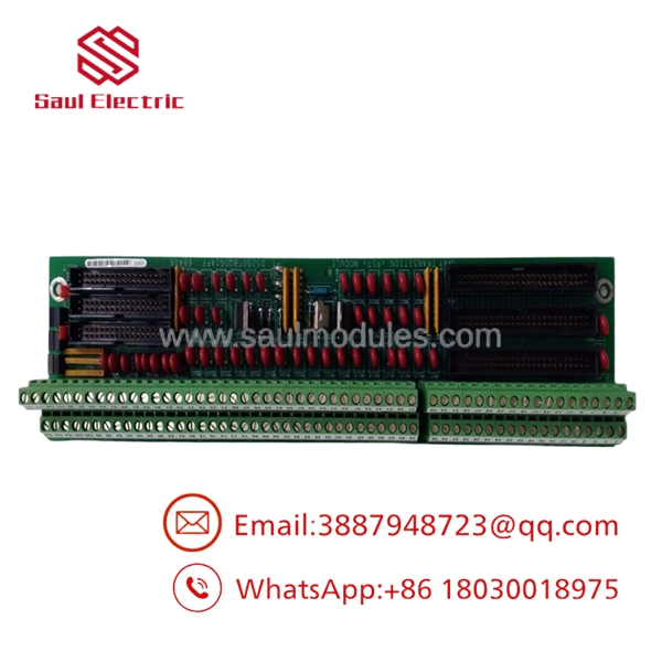
DS200TBQDG1AFF
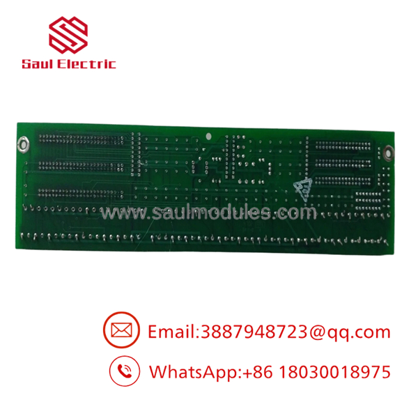
DS200TBQDG1AFF
The Veteran’s Tech Trap Guide
- ⚠️ Document Hardware Jumpers First: The DS200TBQDG1AFF uses hardware jumpers to configure signal conditioning pathways (e.g., current vs. voltage inputs, shield grounding options). Take a clear photo and document all jumper settings on your old board before removal. A mismatched jumper can blind your core processor to a 4-20mA feedback loop.
- ❗ Never Disconnect Under Power: The ribbon cable headers on this board link directly to ADC and DAC circuits on the main processor cards. Unplugging a ribbon cable while the Mark V rack is energized can introduce voltage spikes that destroy input channels on upstream core boards.
- ⚠️ Mind the Shield Wire Landing: Analog signals are extremely sensitive to ground loops. Ensure field cable drain/shield wires are landed strictly on the designated ground terminals as mapped by the original GE installation drawings—do not double-ground both ends.
- ❗ Inspect the “AFF” Suffix: The “AFF” suffix designates specific factory revision levels. While older suffix boards (like G1A) might fit physically, minor circuit layout updates or onboard passive value changes on later revisions could affect sensitive LVDT calibration constants.
Frequently Asked Questions
- Q: Is the GE DS200TBQDG1AFF hot-swappable?
- A: No. Pulling this card or its attached ribbon cables while powered will disrupt active analog control loops and likely trip the turbine. Always de-energize the cabinet before replacing hardware.
- Q: What signals pass through the DS200TBQDG1AFF board?
- A: This board primarily handles high-priority analog field signals, including LVDT/RVDT valve position feedback, 4-20mA control outputs, servo valve drive signals, and various transmitter inputs.
- Q: What is the difference between revision G1A and G1AFF?
- A: “G1” defines the artwork design group, while “AFF” represents subsequent engineering revisions made by GE to improve noise immunity and component reliability. G1AFF is backward compatible with earlier G1 series revisions in nearly all applications.
- Q: Do I need to recalibrate my valves after replacing this card?
- A: Yes. Because slight component tolerances exist between analog boards, you should always re-verify LVDT/RVDT zero and span calibrations via your Mark V operator interface after installing a replacement board.
- Q: What warranty is included with this surplus card?
- A: We provide a full 12-month replacement warranty on all New Surplus and Refurbished GE Mark V boards.
- Q: Why purchase surplus instead of ordering directly from the OEM?
- A: The GE Speedtronic Mark V platform is legacy equipment. OEM lead times are often long or non-existent for discontinued models. Sourcing tested surplus gets your plant back online in days instead of months, at a significantly reduced cost.




 Start Chat


