





Description
Product Introduction
The GE DS200TCCBG1BED operates as a Common Extended Analog I/O Board (TCCB) within the GE Speedtronic Mark V turbine control system. Functioning as an expansion node for complex control architectures, it scales and conditions auxiliary process feedback—including 4–20 mA loops, 0–1 mA signals, Resistance Temperature Detectors (RTDs), and potential/current transformer (PT/CT) inputs—before passing them to primary processor cards.
Driven by an onboard 80196 microprocessor and configurable PROM chips, the TCCBG1BED executes local signal conditioning to reduce processing load on core control racks. This board design provides the high-accuracy analog conditioning required for generator voltage monitoring, line current tracking, and critical bearing temperature protection across power plants.
Key Technical Specifications
| Parameter | Specification |
| Manufacturer | General Electric (GE) |
| Part Number | DS200TCCBG1BED |
| System Compatibility | Speedtronic Mark V Control System |
| Board Acronym | TCCB (Common Extended Analog I/O Board) |
| Processor | Intel 80196 Microprocessor |
| Firmware Memory | Socketed, removable PROM chips (transferable from old card) |
| Signal Inputs | 4-20mA / 0-1mA, RTD inputs, PT & CT voltage/current lines |
| Key Bus Connectors | 3PL (Data bus to STCA/TCCA), 2PL (Power from TCPS) |
| Field Connectors | JHH (mA Inputs), JII (RTD Inputs), JMP (PT/CT Signals) |
| Power Supply | +5V DC via 2PL connector |
| Operating Temperature | -30°C to +65°C (-22°F to +149°F) |
Application Scenarios & The “Trench” Experience
During a high-demand run on a combined-cycle power block, the Mark V panel generates a sudden analog input mismatch alarm on the generator stator monitoring system. Diagnostic codes indicate erratic line current and PT voltage telemetry. Troubleshooting reveals severe analog-to-digital converter drift on the original TCCB board, threatening an automatic unit trip. Swapping in a bench-tested DS200TCCBG1BED card—and swapping the existing socketed PROMs over—restores precise PT/CT tracking without needing an extensive re-flash of site constants.
- Power Generation Facilities – Generator & Bus Voltage Monitoring – Pre-conditions PT and CT inputs to deliver precise voltage and current feedback for excitation control.
- Gas & Steam Turbine Protection – Exhaust & Bearing Temperature Loops – Processes multi-channel RTD inputs to manage thermal ramps and protect against bearing damage.
- Industrial Cogeneration – Auxiliary Process Loops – Conditions 4–20 mA field signals from pressure transmitters and fuel flowmeters.
Transparency SOP: Quality Assurance & Testing
We don’t just ship boxes; we test them on actual GE Mark V racks.
- Inbound Visual Inspection: Microscopic trace audit checking for thermal damage, cold solder joints, bent connector pins, and pristine PROM sockets.
- PROM Socket & Chip Audit: Pins on the chip sockets are tested for structural tension and oxidation to guarantee reliable IC contact.
- Power Rail Bench Check: Applying clean +5V DC supply power to verify onboard voltage regulation and 80196 CPU boot initialization.
- Channel Signal Injection: Injecting calibrated 4-20mA, RTD, and PT/CT millivolt signals across connectors JHH, JII, and JMP to verify input accuracy.
- Anti-Static Packaging: Vacuum-sealed in an ESD shielding bag accompanied by fresh desiccant prior to protective foam boxing.
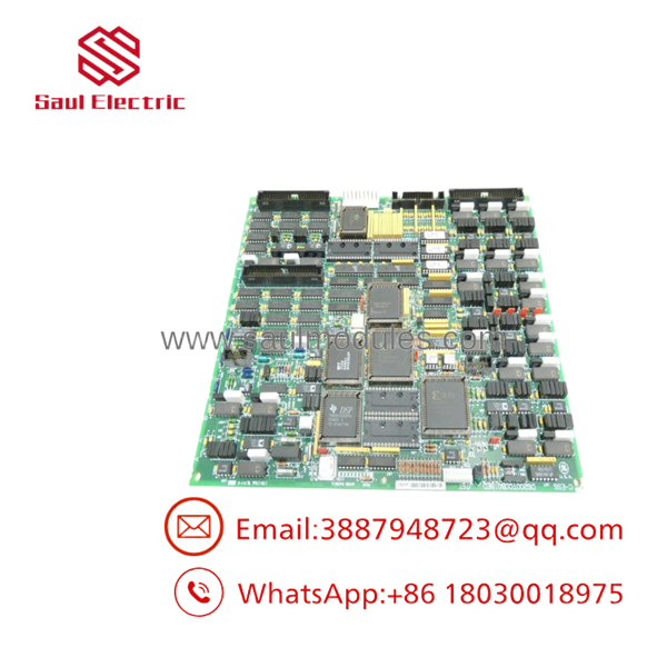
DS200TCCBG1BED
The Veteran’s Tech Trap Guide (Crucial Value-Add)
- ⚠️ YOU MUST MOVE YOUR EXISTING PROMs: To be honest, this is where 90% of field techs trip up. The replacement board comes with default or blank software. You must carefully extract the socketed PROM chips from your old failed board and insert them into the exact same sockets on the replacement board to retain site-specific configurations.
- ❗ Watch Out for Chip Pin Alignment: When transferring PROMs, use an IC extractor tool. Pushing a chip in with a bent pin will crush the leg, corrupt system bootup, and potentially destroy the firmware chip.
- ⚠️ Map the Hardware Jumpers (J1 through J5): Jumpers J1 through J5 configure the board for generator/bus voltage and line current monitoring. Take a high-resolution photo of the jumper positions on your old board and mirror them pin-for-pin before applying power.
- ❗ Never Disconnect Under Power: Disconnecting 50-pin ribbon connectors (JCC, JDD) or bus connectors (3PL) while the cabinet is live can damage the onboard 80196 processor and trip adjacent core cards. De-energize the rack first.
Frequently Asked Questions (FAQ for Conversion)
Q: Do I need ControlSim or an HMI programmer to configure a new DS200TCCBG1BED board?
A: Generally, no—provided you transfer the socketed PROM chips from your original card. The operating firmware and baseline logic reside on those chips. However, any fine-tuning of I/O constants can still be adjusted via the Mark V I/O Configuration Editor if necessary.
Q: What is the purpose of hardware jumper J14 on this board?
A: Hardware jumper J14 is factory-designated to connect the board’s internal RS-232 serial interface port directly to DCOM for diagnostic communication.
Q: What does the “BED” suffix indicate on this part number?
A: The BED suffix indicates specific hardware revision levels (B, E, and D) reflecting artwork updates, trace optimization, and component sourcing improvements over earlier G1 baselines.
Q: Can I use this card in place of an older DS200TCCBG1 parent board?
A: Yes. The G1BED board is backward compatible with earlier G1 revisions. Just ensure that all DIP switches, hardware jumpers, and PROM software chips match your original cabinet configuration.
Q: What warranty coverage is included with this module?
A: Every unit comes backed by a full 12-month replacement warranty from the date of shipment, covering onboard processing components, channel accuracy, and hardware reliability.




 Start Chat


