





Description
Product Introduction
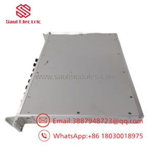
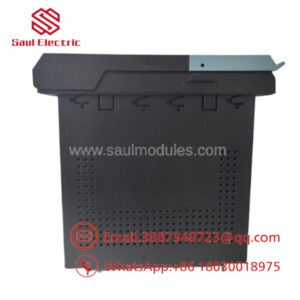
The GE DS200TCCBG3B is a dedicated Common Extended Analog I/O Board (TCCB) built explicitly for GE Speedtronic Mark V gas/steam turbine control systems and legacy TC2000 drive architectures. Located within the core control rack (such as the P1 core or R5 core loops), it interfaces with the TBCB terminal board and TCEB expansion card to handle high-level power system telemetry.
Unlike general-purpose analog input cards that process standard 4-20mA loop signals, the TCCB board isolates, scales, and conditions critical line current (CT) and bus/generator voltage (PT) inputs. Driven by an onboard Intel 80196 microcontroller, it executes hardware-level signal conditioning before passing clean digital data over the backplane to compute real-time megawatt (MW), power factor (PF), and reactive power (VAR) calculations.
Key Technical Specifications
| Parameter | Specification / Value |
| Manufacturer | General Electric (GE) |
| System Architecture | Speedtronic Mark V Gas/Steam Turbine Control |
| Board Functional Acronym | TCCB (Common Extended Analog I/O Board) |
| Onboard Microprocessor | Intel 80196 16-bit Microcontroller |
| Signal Scaling Inputs | Bus/Generator Voltage (PT), Line Current (CT), RTD, 4-20mA, 0-1mA |
| Primary Connectors | 50-pin Ribbon Cable Headers (JCC & JDD), 3PL Connector |
| Hardware Configuration | Physical Jumper Blocks (J1 to J5 for PT/CT scaling, J14 for DCOM serial) |
| Status Indication | Single Green LED visible via front edge slot (Power/Self-Test) |
| Memory Architecture | Socketed PROM/EPROM chips for localized firmware execution |
| Form Factor / Dimensions | Standard Mark V PCB footprint (~21.2 cm x 15 cm) |
Application Scenarios & The “Trench” Experience
The Trench Story
It’s 3:00 AM at a 2×1 combined cycle plant. Turbine #2 trips out during a grid disturbance because the control system lost generator voltage feedback, throwing a critical transducer fault. The plant is bleeding thousands of dollars per hour in lost generation. Diagnostics trace the issue to failed scaling resistors and a cooked 80196 chip on the legacy TCCB board inside the Mark V core. Standard supply houses quote 6-week lead times for legacy Mark V components. Swapping in a pre-tested, matched-revision DS200TCCBG3B gets the GT back online, synchronized, and tied to the grid before the morning peak demand window.
Industrial Applications
- Power Generation (Gas Turbines): Processing PT/CT inputs on GE Frame 6, 7, and 9 gas turbines for generator synchronization, VAR control, and MW output tracking.
- Steam Turbine Utilities: Managing RTD thermal monitoring and line voltage conditioning on combined-cycle steam plant control loops.
- Industrial Co-generation Plants: Real-time power factor monitoring and load shedding controls via the 0-1mA and 4-20mA extended analog loops.
- Heavy Industrial Drives: Integration within legacy GE TC2000 drive systems for high-horsepower motor speed and voltage regulation.
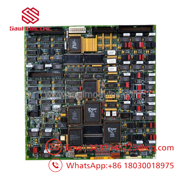
DS200TCCBG3B
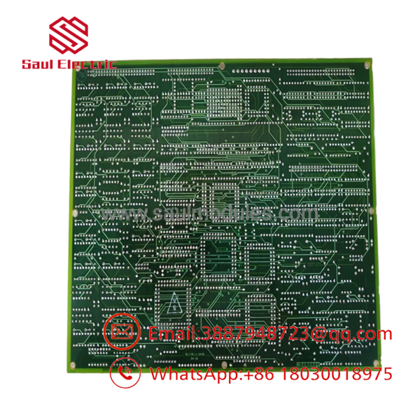
DS200TCCBG3B
Transparency SOP: Quality Assurance & Testing
We don’t just pull legacy boards out of a warehouse box and throw them into a crate; we validate them on live GE Mark V rack setups.
- Inbound Physical Inspection: Complete visual audit under magnification. Inspection for trace corrosion, bulging electrolytic capacitors, damaged ribbon pins (JCC/JDD), and verification of genuine OEM solder profiles.
- Anti-Static ESD Cleaning: Ultrasonic aqueous bath to remove industrial carbon dust and airborne oil film, followed by thermal drying.
- Benchtop Resistance & Diode Checks: Checking point-to-point resistance across PT/CT scaling loops, power rails (+5V, +/-15V), and onboard isolation transformers.
- Live Mark V Core Testing: Board installation into a live Speedtronic Mark V test rig (
<R>,<S>, or<T>core). Verification of green LED self-test, 80196 boot cycle, and communication via the 3PL backplane connector. - Signal Injection Calibration: Injecting precise 4-20mA, RTD resistance curves, and simulated 120V PT signals to verify scale factor accuracy and onboard A/D conversion.
- Firmware Version Logging & Anti-Static Packaging: Documenting all socketed EPROM revision tags before vacuum-sealing the board in anti-static ESD shielding.
The Veteran’s Tech Trap Guide (Crucial Value-Add)
⚠️ 1. The Hardware Jumper Trap (J1 – J5)
Never assume a replacement DS200TCCBG3B is “plug-and-play” out of the box. Jumpers J1 through J5 physically define the PT and CT input scaling ranges. If your old board was set for 115V PT inputs and your replacement board came configured for 69V inputs, you will blind the turbine core to real generator voltage and risk a failed synchronization—or worse, a out-of-phase closure.
Fix: Take a high-resolution photo of every jumper block (J1–J5, J14, J15, J16) on the old board before pulling it, and match the replacement board position-for-position.
❗ 2. Socketed EPROM Swapping
The DS200TCCBG3B uses socketed PROM modules containing system-specific code execution parameters. If your firmware revision on the replacement board doesn’t match the software revision loaded on your Mark V HMI or Stage One processor, the core will drop into a I/O Configuration Fault.
Fix: Carefully transfer your original socketed PROMs to the new card using an IC chip extractor tool. Watch out for bent pins.
⚠️ 3. Ribbon Cable Delamination (JCC & JDD)
The 50-pin ribbon cable headers (JCC and JDD) on these vintage boards become extremely brittle over decades of cabinet heat exposure. Forcefully yanking the ribbon connector can fracture the solder joints on the PCB or pull header pins directly out of the board.
Fix: Use a flathead nylon spudger to gently back the connector shell off the board pins evenly from both sides.
Frequently Asked Questions (FAQ)
Q: Can I hot-swap the DS200TCCBG3B while the Mark V turbine control system is powered up?
A: Absolutely not. Pulling a TCCB card from a live core disrupts the 3PL backplane bus, kills CT/PT signal feeds, and will immediately trigger a protective trip on the turbine. Power down the specific core enclosure and verify zero voltage on the backplane before swapping.
Q: What is the primary functional difference between a TCCA board and a TCCB board?
A: The TCCA board handles general-purpose analog process signals like turbine temperatures, pressure transmitters, and valve positioning. The TCCB (DS200TCCBG3B) handles high-value electrical power system signals—specifically line currents (CTs), generator voltages (PTs), and bus voltages used for grid synchronization and MW/VAR/PF calculations.
Q: What does the ‘G3B’ suffix in the part number signify?
A: In GE Mark V nomenclature, G3 represents the specific artwork and hardware group revision, while B represents the functional circuit revision level. A includes updated component layouts and bug fixes over the original G1 or G2 board variants.
Q: How do I know if the board’s onboard microprocessor is running normally?
A: Check the green edge LED. Upon core power-up, the LED should flash during initial power-on self-tests (POST) and then remain solid green, indicating the Intel 80196 processor has booted successfully and is communicating across the backplane. A dark or constantly flashing LED signals a hardware processor fault or improper power feed.
Q: What warranty is supplied with your surplus and refurbished stock?
A: Every module shipped carries a full 12-month replacement warranty. If a board fails under normal operating conditions within one year of installation, we replace it immediately from our stock.

 Start Chat


