





Description
Product Introduction & Engineering Value
The DS200TCDAH1B is designed for the Mark V turbine-control system’s digital signal-processing layer. It receives contact and pulse information from terminal boards, processes the signals through onboard logic, and provides relay outputs to associated control circuitry.
This is a board where configuration details matter. The TCDA communicates with other Mark V boards through the I/O architecture, and its terminal-board connections determine how field signals reach the control system. Match the full DS200TCDAH1B identifier and associated terminal-board arrangement before replacement.
Technical Specifications
| Parameter | Specification |
|---|---|
| Manufacturer | General Electric |
| Part Number | DS200TCDAH1B |
| Series | Mark V Speedtronic |
| Functional Acronym | TCDA |
| Product Type | Digital I/O Board |
| Digital Inputs | 32 |
| Pulse Accumulator Inputs | 8 |
| Relay Outputs | 10 |
| Terminal Boards | DTBC / DTBD |
| Processor | Intel 80196 |
| Programmable Logic | EPLD |
| RAM | 2 × 32-bit RAM blocks |
| Relay Drivers | 2 × 50-pin connectors |
The board has four 34-pin connectors, including a ribbon-cable interface to the DTBC terminal board and connections associated with the DTBD terminal board. It also includes two 12-pin connectors, two 50-pin connectors, and one 50-pin connector associated with relay outputs.
The TCDA also contains an Intel 80196 microprocessor, programmable logic devices, multiple LEDs, and configuration hardware. The available documentation identifies DS200TCDAH1B as a later revision of the DS200TCDAH1A.
Field Application & the “Trench” Experience
A turbine control cabinet starts showing an intermittent discrete-input fault. The field contact itself tests correctly, but the Mark V diagnostic intermittently changes state.
The maintenance engineer checks the terminal board first, then the ribbon cable and connector seating. Only after those checks does the team inspect the DS200TCDAH1B. The spare is compared against the installed board, including revision and connector layout, before being installed.
That sequence avoids a common Mark V mistake: treating every I/O fault as a failed PCB. The signal path includes the field device, terminal board, cable, TCDA, and controller. Any one of those can produce the same symptom.
Specific application scenarios:
- Mark V turbine discrete permissive/interlock monitoring
- Pulse-speed input acquisition for rotating equipment
- Digital trip and status signal processing
- Relay output control in GE turbine auxiliary systems
- Legacy Mark V I/O cabinet refurbishment
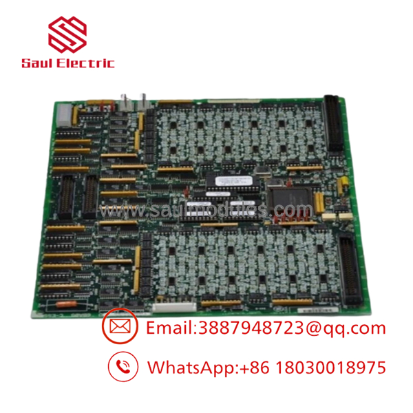
DS200TCDAH1B
Transparency SOP: QA & Testing
For DS200TCDAH1B, a proper QA process should cover both logic and I/O behavior:
- Identity verification — Confirm DS200TCDAH1B and revision markings.
- PCB inspection — Check connectors, relays, LEDs, ICs, solder joints, and board traces.
- Terminal-board compatibility — Verify the associated DTBC/DTBD arrangement.
- Digital-input testing — Exercise representative digital channels and verify state detection.
- Pulse-input testing — Verify the applicable pulse-accumulator channels using controlled frequency signals.
- Relay testing — Confirm relay outputs and associated driver circuits operate correctly.
- Processor/logic verification — Where compatible Mark V test equipment is available, verify onboard logic and diagnostics.
- Final QA — Record actual-unit photographs, test results, revision, condition, and warranty status.
For New Surplus, confirm that the board has never been installed or energized. For Refurbished, request channel-level functional-test information rather than accepting only a generic inspection statement.
The Veteran’s Tech Trap Guide
⚠️ Trap #1 — Don’t confuse DS200TCDAH1B with a generic TCDA.
The complete part number and revision should be matched. Mark V boards can look nearly identical while having different hardware configurations.
⚠️ Trap #2 — Check the terminal-board path.
The TCDA works with DTBC and DTBD terminal-board arrangements. A good PCB cannot compensate for an incorrect terminal-board or cable configuration.
⚠️ Trap #3 — Don’t ignore pulse inputs.
A pulse-accumulator problem may look like a generic digital-input failure. Verify frequency-related channels separately when troubleshooting speed or pulse feedback.
PRO TIP: Before removing the original TCDA, photograph every ribbon-cable connector and terminal-board connection. Mark V cabinets often contain several closely related I/O interfaces.
Dynamic FAQ
Q: What is the GE DS200TCDAH1B?
A: It is a GE Mark V TCDA Digital I/O Board providing 32 digital inputs, 8 pulse-accumulator inputs, and 10 relay outputs.
Q: Which terminal boards are associated with the TCDA?
A: The documented architecture identifies DTBC and DTBD terminal boards.
Q: What processor does the board use?
A: The technical documentation identifies an Intel 80196 microprocessor along with programmable logic and RAM resources. (manuals.plus)
Q: Can replace DS200TCDAH1A?
A: The B revision is documented as a later revision of the A version, but system-specific compatibility should still be verified against the Mark V documentation before substitution. (manuals.plus)
Q: How should New Surplus authenticity be verified?
A: Request photographs of the actual board, the complete part-number marking, confirmation of unused status, and information confirming whether it has ever been energized.
Q: What should I request for Refurbished stock and warranty?
A: Ask for digital-input, pulse-input, relay-output, and processor/logic testing details, plus the refurbishment scope and written warranty/DOA terms. A generic “tested” statement is not enough for a critical Mark V I/O board.


 Start Chat


