





Description
Product Introduction & Engineering Value
The TCTG is part of the turbine protection path, where relay logic and trip signals have a direct relationship with turbine shutdown functions. It is therefore a protection-oriented board, not a general-purpose digital I/O card.
The board carries 21 plug-in relays, along with three 50-pin and two 12-pin connectors. The connector and relay arrangement should be checked against the installed board before replacement.
Technical Specifications
| Parameter | Specification |
|---|---|
| Manufacturer | General Electric |
| Part Number | DS200TCTGG1AFF |
| Series | Mark V |
| Functional Acronym | TCTG |
| Functional Description | Simplex Trip Board |
| Application | GE turbine control |
| Functional Revision 1 | A |
| Functional Revision 2 | F |
| Artwork Revision | F |
| PCB Coating | Normal coating |
| Plug-in Relays | 21 |
| 50-Pin Connectors | 3 |
| 12-Pin Connectors | 2 |
The three 50-pin connectors are identified as JLY, JLX, and JLZ, while the two 12-pin connectors are JN and JM. The 21 plug-in relays use K-designations and are retained mechanically with metal straps.
Protection architecture
The broader TCTG architecture is associated with turbine trip functions, including primary and emergency trip relay paths. One technical reference describes primary trip relays as being controlled through the core control system and emergency trip relays through TCEA-related logic.
Important: Do not treat third-party listings that claim specific input voltages, output voltages, current ratings, IP ratings, or safety certifications as authoritative for this exact PCB. Several current listings contain conflicting specifications. The reliable identification is the GE part number and Mark V functional designation.
Field Application & the “Trench” Experience
A turbine is being prepared for a controlled restart following maintenance. During the pre-start sequence, the trip circuit does not reset as expected. The field devices check out, and the maintenance team begins tracing the protection chain.
The technician finds the DS200TCTGG1AFF and documents every relay position, connector, and board marking before touching the hardware. The replacement is checked against the original G1AFF configuration. Only after the trip circuitry and associated signals are verified is the board returned to service.
That is the correct mindset for a trip board. A nuisance trip can stop a machine; a wrongly configured replacement can compromise the protection logic itself.
Specific application scenarios:
- Gas-turbine emergency trip circuitry
- Steam-turbine turbine-trip interface systems
- Fuel shutoff and turbine shutdown logic
- Mark V pre-start trip-permissive circuits
- Legacy Speedtronic protection cabinet refurbishment
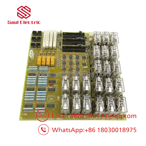
DS200TCTGG1AFF
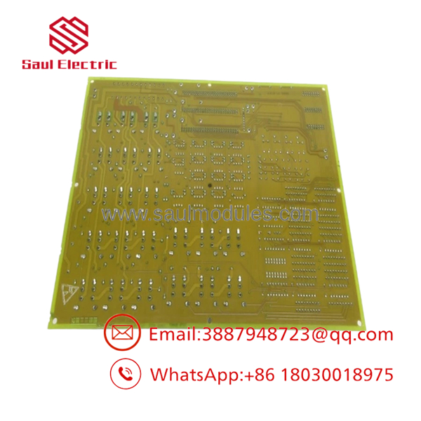
DS200TCTGG1AFF
Transparency SOP: QA & Testing
For DS200TCTGG1AFF, testing should concentrate on relay operation and protection-path integrity:
- Identity verification — Confirm the complete
DS200TCTGG1AFFnumber and A/F/F revision sequence. - Physical inspection — Inspect the PCB, relay sockets, connectors, traces, solder joints, and components.
- Relay inspection — Check all 21 plug-in relays and their retaining straps.
- Connector inspection — Verify the three 50-pin and two 12-pin interfaces.
- Relay functional testing — Exercise each applicable relay using an approved test procedure.
- Trip-path verification — Confirm the correct relay logic and contact behavior.
- System integration testing — Verify the trip circuit with the associated Mark V hardware before returning the turbine to operation.
- Final QA record — Document actual-unit photographs, relay-test results, board revision, condition, and warranty.
For New Surplus, require confirmation that the actual board has never been installed or energized. For Refurbished, request relay-level test results rather than a generic power-on statement.
The Veteran’s Tech Trap Guide
⚠️ Trap #1 — Don’t confuse TCTG with an ordinary relay-output board.
The TCTG is associated with turbine trip functions. Protection-circuit testing needs to be treated differently from routine PLC output verification.
⚠️ Trap #2 — Count the relays and check their positions.
The documented configuration contains 21 plug-in relays. Their positions and associated wiring should be recorded before removing the original board.
⚠️ Trap #3 — Verify the complete G1AFF suffix.
GE’s Mark V inventory includes several TCTG variants, including DS200TCTGG1A, DS200TCTGG1AEC, DS200TCTGG1AEE, DS200TCTGG1AFF, and DS200TCTGG2A. They should not be treated as interchangeable without engineering verification.
PRO TIP: Before replacement, create a relay map showing relay designation + wire destination + normal state. That record can save considerable troubleshooting time during commissioning.
Dynamic FAQ
Q: What is the GE DS200TCTGG1AFF?
A: It is a GE Mark V TCTG Simplex Trip Board used in turbine trip and protection-related circuitry.
Q: How many relays are installed on the DS200TCTGG1AFF?
A: The documented board configuration has 21 plug-in relays.
Q: What connectors does the board use?
A: The documented configuration includes three 50-pin connectors—JLY, JLX, and JLZ—and two 12-pin connectors, JN and JM.
Q: Is interchangeable with DS200TCTGG1AEC or DS200TCTGG1AEE?
A: Do not assume interchangeability. These are separately identified TCTG configurations. Match the complete part number, revision, relay arrangement, wiring, and applicable Mark V documentation.
Q: How should New Surplus authenticity be verified?
A: Request actual-unit photographs showing the complete identification, relay configuration, and board condition. Also obtain written confirmation that the board has never been installed or energized.
Q: What should I request for Refurbished stock and warranty?
A: Request the refurbishment scope, individual relay testing, connector inspection, trip-path testing, actual-unit photographs, serial/part-number traceability, and written warranty/DOA terms. A simple “powers on” test is not meaningful enough for a turbine trip board.



 Start Chat


