





Description
Product Introduction
The GE DS6815PCLG1B1A is a Phase Control and Logic Module (PCLG) belonging to General Electric’s DS6800/DS6815 industrial drive and turbine control system families. Engineered for high-demand power regulation environments, this card bridges low-voltage digital control loops with high-power thyristor (SCR) gate firing circuits.
Operating within generator static exciters, DC motor starters, and heavy industrial drives, the PCLG board tracks incoming AC line phase angles and locks onto zero-voltage crossings. It calculates precise phase-angle delays to deliver clean, jitter-free firing commands to SCR power bridges, maintaining balanced current output while protecting upstream power distribution from harmonic distortion and phase imbalances.
Key Technical Specifications
| Parameter | Specification / Value |
| Manufacturer | General Electric (GE) |
| System Architecture | DS6800 / DS6815 Industrial Drive & Speedtronic Control Racks |
| Board Functional Acronym | PCLG (Phase Control & Logic Board) |
| Primary Function | AC phase-angle synchronization, zero-crossing detection, and SCR firing pulse routing |
| Timing Logic | Phase-Locked Loop (PLL) array with hardware-level zero-crossing comparators |
| Signal Inputs | 3-phase voltage sense feedback via external isolation transformers |
| Board Form Factor | Extended PCB profile with dual card-edge backplane connectors |
| Hardware Configuration | Physical BERG jumpers / DIP switches for nominal frequency (50/60 Hz) and phase sequence |
| Operating Temperature | -30°C to +65°C Industrial Extended Range |
Application Scenarios & The “Trench” Experience
The Trench Story
It’s 2:15 AM at a regional power plant. A static exciter cubicle feeding a peak-demand generator trips unexpectedly on a “Phase Synchronization Fault” during a reactive load ramp. Technicians verify that incoming AC grid power is balanced, but output firing pulses to the SCR power bridge are erratic. Inspection reveals that aging operational amplifiers and thermal drift in timing capacitors on the original PCLG board caused it to lose phase-lock synchronization. Swapping in a pre-tested DS6815PCLG1B1A replacement module and configuring the 60 Hz line frequency jumpers restores clean zero-crossing detection, clearing the fault and allowing the generator to return to the grid.
Industrial Applications
- Generator Static Excitation Systems: Synchronizing thyristor bridge firing commands with generator terminal voltage in power plant exciter panels.
- Large Industrial DC Motor Drives: Regulating heavy armature and field current supplies in metal rolling mills and mining hoists.
- Gas & Steam Turbine Controls: Managing phase-fired starters and turning gear motor controls on heavy-duty GE turbine units.
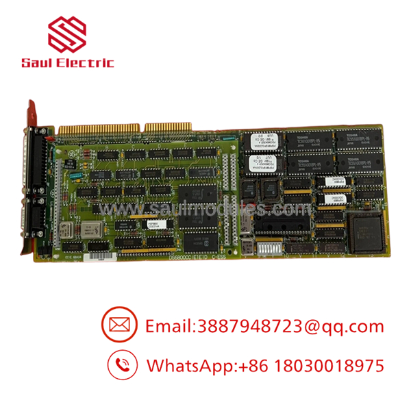
DS6815PCLG1B1A
Transparency SOP: Quality Assurance & Testing
Every legacy phase control module undergoes a strict, multi-stage reconditioning and dynamic timing validation protocol before dispatch:
- Inbound Physical Inspection: Detailed optical audit under magnification for thermal trace stress, aging electrolytic capacitors, physical connector wear, and component discoloration.
- Ultrasonic ESD Cleaning: Deep solvent wash to remove conductive carbon dust, oil film, and chemical residues accumulated over decades of cabinet operation.
- Phase-Locked Loop (PLL) & Timing Audit: Injecting 3-phase AC reference signals (50 Hz and 60 Hz) to verify zero timing jitter and clean zero-crossing response on an oscilloscope.
- Gate Firing Output Drive Test: Exercising output pulse transformers under electrical load to ensure uniform pulse amplitude and rapid rise times across all firing channels.
- Live System Rack Execution: Installing the card into an active test rack cage to confirm backplane communications handshaking and diagnostic indicator states under full load.
- Jumper Audit & ESD Packaging: Documenting all physical BERG jumper settings before vacuum-sealing the board in static-shielding packaging.
The Veteran’s Tech Trap Guide (Crucial Value-Add)
⚠️ 1. 50 Hz / 60 Hz Line Frequency Jumpers
The DS6815PCLG1B1A utilizes physical BERG jumper blocks or DIP switches to establish nominal AC line frequency (50 Hz vs. 60 Hz) and phase rotation. Installing a replacement board without matching the original jumper configuration will cause immediate loss of phase-lock, resulting in SCR misfiring or trip alarms.
Fix: Photograph all jumper blocks on your failed board before removal, and match every setting position line-for-line on the replacement board.
❗ 2. Card-Edge Contact Cleaning
Because firing pulse synchronization relies on clean, low-voltage analog timing signals, oxide buildup on the backplane card-edge gold contacts can introduce signal noise or phase jitter.
Fix: Clean the card-edge contacts gently using an isopropyl alcohol swab before seating the board. Avoid coarse abrasive pads that can strip the thin gold plating.
⚠️ 3. Revision Suffix Parity (1B1A)
The trailing revision code 1B1A indicates specific artwork enhancements, component wattages, and elevated noise immunity compared to earlier 1A revisions. Matching the complete alphanumeric part number ensures direct electrical and physical drop-in compatibility.
Fix: Cross-reference the entire part number stamped on the PCB edge margin prior to ordering.
Frequently Asked Questions (FAQ)
Q: Can I hot-swap the DS6815PCLG1B1A board while the drive system is under power?
A: No. Removing or inserting a phase control board live can interrupt gate firing timing, causing abrupt voltage spikes across power SCRs or instantly tripping the main drive breaker. Always isolate control cabinet power prior to servicing.
Q: What is the most common failure mode on this board?
A: Drift in analog timing components (capacitors and op-amps) due to prolonged thermal exposure inside sealed cabinets, leading to phase-lock loss, un-balanced bridge currents, or zero-crossing fault alarms.
Q: Does this card require software programming or laptop configuration after installation?
A: No. The DS6815PCLG1B1A is a pure hardware-level logic and phase control board. It operates using analog phase-lock loops and physical jumpers—no software downloading or firmware flashing is required.
Q: What is the difference between DS6800/DS6815 and DS200 part series?
A: DS6800/DS6815 series boards belong to classic GE system drives and controls featuring card-edge connector formats. DS200 series boards belong to newer platforms (like Mark V) that utilize multi-pin ribbon cable headers. They are not interchangeable.
Q: What warranty is supplied with surplus and refurbished stock?
A: Refurbished and new-surplus DS6815PCLG1B1A boards typically carry a standard 12-month replacement warranty covering component failure under normal operating conditions.


 Start Chat


