





Description
Product Introduction & Engineering Value
Field wiring errors and loose terminal strips account for more unexpected downtime during commissioning than almost any software bug. The GE VersaMax IC200CHS022 tackles wiring reliability head-on by functioning as the foundational mounting block and backplane bridge for VersaMax I/O modules. Designed with 32 box-style screw terminals, it accepts solid or stranded wire sizes ranging from 14 to 22 AWG, locking field conductors securely into place.
Because VersaMax architecture separates the field wiring carrier from the active electronic module, the IC200CHS022 lets electricians pre-wire control panels long before logic modules arrive on site. When maintenance is required, active cards snap in and out of the carrier without touching a single field wire terminal, preserving loop integrity and slashing mean time to repair (MTTR).
Technical Specifications
| Parameter | Specification |
| Compatible Platform | GE VersaMax I/O Modules (Discrete & Analog) |
| Terminal Type | Box-style screw terminals (Captive screws) |
| Number of Terminals | 32 field connection points + Backplane bus pass-through |
| Wire Gauge Range | 14 AWG to 22 AWG (Solid or Stranded copper) |
| Maximum Current Capacity | 2 Amps per terminal point / 10 Amps total continuous carrier capacity |
| Voltage Isolation | 250 VAC continuous terminal-to-terminal / 1500 VAC to DIN rail |
| Mounting Format | 35mm DIN Rail (EN 50022) or Panel Mount via screw holes |
| Keying Mechanism | Built-in module keying dial (prevents inserting wrong module type) |
| Backplane Interconnect | Integrated male/female local expansion bus connectors |
| Dimensions (W x H x D) | 134mm x 67mm x 70mm |
Field Application & The “Trench” Experience
During a critical midnight retrofit at a grain processing facility, an operator accidentally backed a forklift into an exposed remote I/O junction box, shearing off the housing of a 32-point discrete output carrier. The PLC backplane was severed, taking half the conveyance lines offline. We pulled a fresh IC200CHS022 from local surplus stock, snapped it onto the DIN rail, landed all 32 field conductors into the marked box terminals, and clicked the existing output module back in place—restoring full backplane continuity and motor starter control in under 35 minutes.
Niche Application Scenarios:
- High-Density Control Panels: Pre-wiring 32-point discrete input signals in tight marshalling cabinets where space prevents using dual-tier carriers.
- Modular Skid Assemblies: Building OEM skids where field wiring harnesses must be terminated and tested prior to installing sensitive PLC logic modules.
- Vibration-Prone Industrial Environments: Securing solid or ferruled stranded wires in box-clamp terminals on rock crushing and mining equipment.
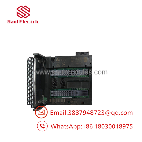
- IC200CHS022
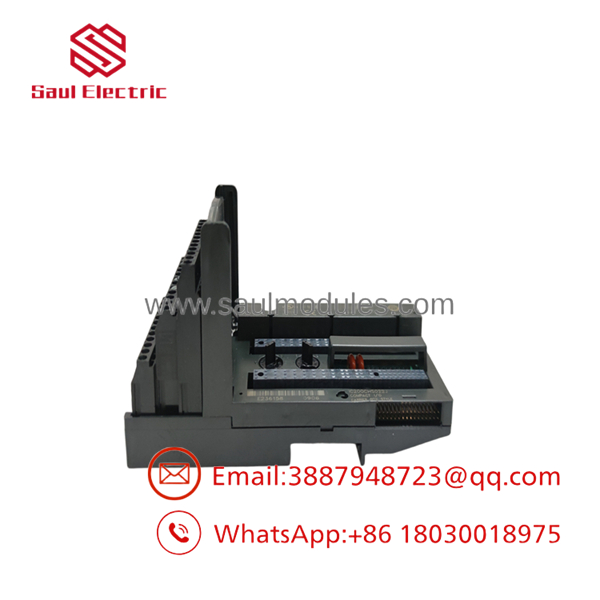
- IC200CHS022
Transparency SOP: QA & Testing
To guarantee that our New Surplus and Remanufactured IC200CHS022 carriers provide flawless electrical continuity and mechanical alignment, every base passes a 5-step bench audit:
- Physical & Terminal Inspection: Magnified inspection of all 32 box terminal screws, checking for stripped threads, bent wire clamps, or cracked housing plastics.
- Backplane Connector Audit: Inspection of the male and female edge connector pins for oxidation, pin misalignment, or board-level trace damage.
- Multi-Point Continuity Test: Ohm-meter check verifying zero-resistance continuity from every terminal block pin to the module socket interface.
- Mechanical Lock & Keying Validation: Testing the module insertion latching mechanism and verifying that the module keying selector dial rotates smoothly across all positions.
- Bus Alignment Stress Test: Connecting the carrier between two active VersaMax bases in a live test rack to verify backplane bus pass-through under full data load.
The Veteran’s Tech Trap Guide
- ⚠️ Set the Module Keying Selector! Before plugging an active I/O module into the , you must set the mechanical keying dial on the carrier to match the module type. Forcing a module into a carrier with mismatched keying can snap internal alignment pins or damage sensitive backplane connectors.
- PRO TIP: Torque Screws to Spec! The box clamp screws on the should be torqued to 5.3 to 7.0 in-lbs (0.6 to 0.8 Nm). Over-tightening can strip the plastic housing threads, while under-tightening will lead to intermittent open circuits on vibrating machinery.
- ⚠️ Current Limit Watch: While individual terminals handle up to 2 Amps, the entire carrier base has a cumulative continuous current limit (typically 10A max across common power groups). If switching high-draw solenoid banks, distribute power legs across multiple power-feed terminals!
Dynamic FAQ
Q: What is the primary difference between the and the IC200CHS002 carriers?
A: The features compact box-style screw terminals for high-density wiring, whereas the IC200CHS002 utilizes two rows of standard barrier-style screw terminals.
Q: Can I replace an without shutting off system power?
A: Replacing the passive carrier requires disconnecting field wiring and interrupting the local backplane bus, so the VersaMax rack power should be de-energized during carrier replacement. However, inserting or removing an I/O module from the carrier can be done under power if local safety regulations allow (Hot Swap/RIUP).
Q: Does the include the backplane extension cable?
A: No. The snaps directly onto adjacent VersaMax carriers via integrated side-mounting connectors. If you need to jump to another row of DIN rail, a separate VersaMax expansion cable (e.g., IC200CBL500 series) is required.
Q: Are these units tested and covered under warranty?
A: Yes. Every base undergoes thorough mechanical and electrical continuity testing and comes backed by a comprehensive 1-Year replacement warranty.

 Start Chat


