





Description
Product Introduction & Engineering Value
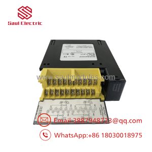
When you are maintaining distributed I/O across a busy plant, the last thing you want to do during a module swap is disconnect thirty individual field wires. The GE Fanuc IC670CHS002 terminal block acts as the mechanical and electrical anchor for Field Control stations. By routing all I/O, power distribution, and backplane ribbon communications directly into this base, GE made field electronics completely modular.
This two-slot box-terminal base allows engineers to mount or replace any combination of Field Control digital, analog, or specialty modules without touching a single field screw. Featuring captive screw clamps, direct 35mm DIN-rail grounding springs, and isolated common power distribution groups, the IC670CHS002 keeps wiring tidy while protecting signal integrity in high-vibration environments.
Technical Specifications
- Module Capacity: Accommodates up to two (2) Field Control I/O modules
- Terminal Connection Style: 2-tier box-style clamp terminals
- Wire Range Capacity: Single wire #14 AWG (2.1 mm^2), or two wires #18 AWG (0.86 mm^2) to #22 AWG (0.35 mm^2) copper
- Wire Temperature Rating: Requires copper wire rated for 90°C (194°F) minimum
- Maximum Current Rating: 10 Amps maximum through any single terminal point
- Common Groups (per module slot):
- Group A: Internally tied common terminals (typically DC positive/AC line)
- Group B: Internally tied common terminals (typically DC return/AC neutral)
- Group E: 5 internally tied earth/application common terminals (isolated from A, B, and I/O points)
- Terminal Screw Tightening Torque: 4.5 in-lbs (0.5 Nm)
- Mounting Style: Standard 35mm DIN rail with integrated grounding spring and clamp screw
- Operating Temperature: 0°C to 55°C (32°F to 131°F)
Field Application & The “Trench” Experience
The Turbine Hall Ground Loop Nightmare
At a combined-cycle power station, a 16-point discrete input card on a gas turbine lube oil skid kept reporting intermittent false-open faults. The original terminal base was an early non-grounded revision that had suffered physical damage to its internal backplane connector after decades of turbine vibration. Every time a heavy pump kicked on, static buildup on the ungrounded DIN rail induced noise across the backplane bus, causing the Bus Interface Unit (BIU) to drop communication with the rack.
The lead instrument technician pulled the faulty base during a planned outage. Because all field conductors remained labeled and clamped into terminal groups, they transferred the wiring block-by-block onto a fresh IC670CHS002 base equipped with an intact rear DIN grounding spring. The technician tightened the DIN rail clamp screw to bond the base metal strip to the enclosure earth. Signal noise dropped to zero, and the rack has run without a communication drop since.
Typical Application Environments
- Continuous Chemical Processing Panels: Distributing 24V field power to arrays of 2-wire pressure transmitters via isolated A/B common buses.
- High-Vibration Compressor Skids: Securing sensitive analog input cards with dual hold-down screws directly onto the rigid CHS002 frame.
- Distributed Material Handling Drops: Daisy-chaining power across multiple DIN-mounted Field Control drops using the 10A-rated terminal points.
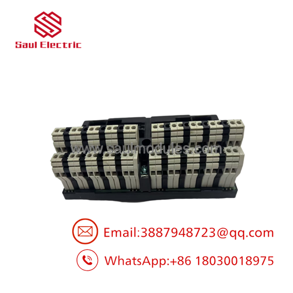
- IC670CHS002
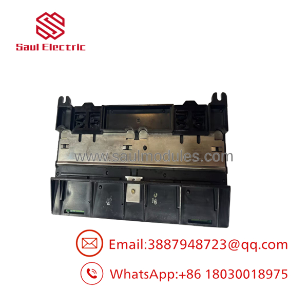
- IC670CHS002
Transparency SOP: QA & Testing
[1. Structural & Pin Inspection] ──> [2. Grounding & Continuity Check] ──> [3. High-Current Stress Test] ──> [4. Live Bus Handshake]
- Structural & Connector Pin Audit: We verify that the DIN latch springs move freely, inspect all 32 box terminal screws for smooth threads, and check backplane male header pins for alignment, bent prongs, or corrosion.
- Grounding & Bus Continuity Verification: Using a milliohm meter, we check the metal grounding strip underneath the base against the DIN clip to ensure resistance is under 0.1 \Omega. Internal A, B, and E common terminal buses are checked for proper internal shorting and inter-group isolation.
- Terminal Current Thermal Check: Sample channels are loaded to 8.0 Amps for two hours to ensure terminal block screws and internal bus copper traces maintain stable thermal profiles under high load.
- Active Backplane Handshake Testing: The base is locked onto a live test rack with a Genius Bus Interface Unit (IC670GBI002) and two I/O modules. We cycle backplane communications and verify that address lines and logic power pass without intermittent bit drops.
The Veteran’s Tech Trap Guide (Crucial Value-Add)
⚠️ TRAP 1: Keying & Slot Compatibility (CHS002 vs. CHS102)
Pay close attention to the revision letter and part suffix of your module! Standard IC670CHS002 bases accept standard Field Control modules. However, if your module catalog number has a suffix of J or higher (e.g.,
IC670ALG230J), it requires a base with an alignment slot, such as the IC670CHS102. Forcing a J-suffix module onto an older CHS002 base without checking the keying tab will bend the module pins or crack the plastic housing!
⚠️ TRAP 2: Forgetting the Rear Grounding Strip Screw
Revisions CHS002B and later feature a rear metal grounding strip that contacts the DIN rail. To satisfy CE and industrial EMC requirements, you must use a grounded, conductive (zinc-plated or unpainted steel) DIN rail and tighten the base clamp screw securely. Mounting this base on painted or aluminum rails without a dedicated earth jumper invites electrical noise directly into your analog backplane signals.
PRO TIP: Daisy-Chaining Terminal Bus Limitations
While the internal A and B common groups make it tempting to jump field power from one slot to the next, remember the hard limit: 10 Amps maximum per terminal point. If you are switching high-draw 120VAC solenoid valves across all 16 points, calculate your total continuous current. If it exceeds 10A, feed power separately into both slots rather than jumpering across the base.
Dynamic FAQ
Q: Can I replace an base without shutting down power to the whole Field Control drop?
A: Standard bases are not rated for hot-swapping the base itself. While individual I/O modules can be hot-inserted into certain keyed bases (like the CHS102) under non-hazardous conditions, replacing the CHS002 base requires removing all field power and disconnecting the backplane ribbon cable to prevent backplane short circuits.
Q: Does the come with the backplane interconnect cable?
A: When purchased as a complete unit, it includes the short multi-pin ribbon cable required to daisy-chain the backplane bus to the adjacent terminal base or Bus Interface Unit (BIU).
Q: What is the difference between box terminals (CHS002) and barrier terminals (CHS001)?
A: The features clamp-style box terminals where stripped wire ends are inserted into a cage and tightened down. The CHS001 uses traditional barrier screw terminals designed for ring or spade lug wire crimps. Both offer identical electrical performance and module capacity.
Q: Are the internal common terminal groups (A, B, and E) connected to each other?
A: No. Group A and Group B are separate internally connected buses intended for power supply distribution. Group E consists of 5 terminals tied together specifically for application shielding/earth grounding and is completely isolated from power and point terminals.
Q: What warranty applies to your new surplus and refurbished bases?
A: All terminal bases—whether refurbished or new surplus—are fully cleaned, backplane tested, and covered by our standard 12-month full-replacement warranty.

 Start Chat


