





Description
Product Introduction & Engineering Value
When managing mixed sinking and sourcing sensors on an aging production line, hardware flexibility is everything. The GE Fanuc IC670MDL640 eliminates the need to buy separate input cards for different field devices by supporting positive and negative logic on a single 16-point block. It mounts onto standard Field Control terminal bases, processing 24 VDC discrete signals from limit switches, proximity sensors, and pushbuttons with built-in noise suppression.
Instead of rewiring control cabinets during a retrofit, dropping in an IC670MDL640 preserves your original layout while maintaining high isolation standards. Onboard input filtering handles mechanical contact bounce, while 1,500 VAC logic-to-field isolation shields the backplane from electrical spikes. It is a dependable workhorse for keeping legacy Genius, Profibus, or DeviceNet Field Control drops operating smoothly.
Technical Specifications
- Number of Channels: 16 discrete inputs (single grouped common)
- Nominal Operating Voltage: 24 VDC
- Input Voltage Range: 0 to 30 VDC
- Logic Type: Positive (Sinking input) or Negative (Sourcing input)
- On-State Voltage Range: +15 to +30 VDC (Positive) / -15 to -30 VDC (Negative)
- Off-State Voltage Range: 0 to +5 VDC (Positive) / 0 to -5 VDC (Negative)
- User Input Current: 7.5 mA per point at 24 VDC (3.0 to 8.0 mA On-state range)
- Input Impedance: 3 k\Omega typical
- Input Filter Response Time: 6 ms typical (10 ms maximum for both ON and OFF transitions)
- Isolation Rating: 1,500 VAC for 1 minute (User-to-Logic and User-to-Frame Ground) / 250 VAC continuous
- BIU Backplane Current Draw: 75 mA typical (all points ON), 83 mA maximum
- Status Indicators: 16 green point LEDs + 1 PWR LED for field/backplane logic
Field Application & The “Trench” Experience
The Bottling Line Proximity Sensor Fault
During a Sunday evening shift at a beverage canning facility, an automated palletizer drop failed to register incoming case positions. The local Genius Field Control node lost input signals on points 1 through 4, bringing the packaging line to a halt. The on-duty maintenance electrician initially suspected failed inductive proximity switches, but voltage checks at the terminal base confirmed 24 VDC was reaching the block terminals.
Further testing revealed that an internal optocoupler array on the original input card had failed due to a recent voltage surge from a shorted solenoid bundle nearby. The technician pulled the damaged module off its IC670CHS002 terminal base—leaving all 16 field wires and common jumpers intact on the cage terminals. After snapping in a spare IC670MDL640, the PWR and point LEDs immediately illuminated. Line communications restored without needing to reconfigure the host PLC software.
Key Deployment Scenarios
- High-Speed Material Handling: Reading PNP and NPN optical sensors along high-vibration conveyor systems.
- Automated Stamping Presses: Interfacing safety light curtains and mechanical rotary limit switches back to a central Genius I/O drop.
- Water & Wastewater Lift Stations: Monitoring float switches, pump run status contacts, and high-level alarms across unconditioned outdoor panels.
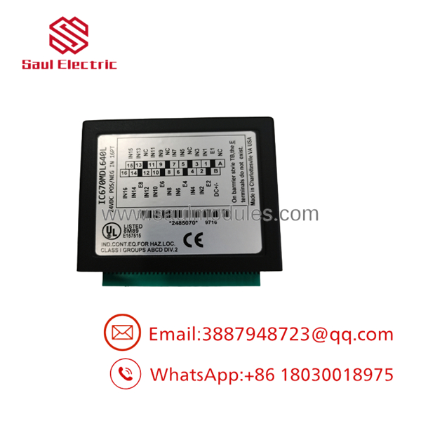
- IC670MDL640
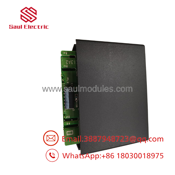
- IC670MDL640
Transparency SOP: QA & Testing
- Step 1: Visual & Pin Integrity Audit
We inspect the card housing for broken retention latches, verify that backplane pin contacts are corrosion-free, and confirm the hardware revision level.
- Step 2: Dual-Logic Voltage Injections
The module is mated to a test base and subjected to full 16-point voltage sweeps using both +24 VDC (sinking) and -24 VDC (sourcing) power configurations. We verify ON/OFF threshold boundaries (V_{ON} \ge 15V, V_{OFF} \le 5V) across all channels.
- Step 3: Response Time & Noise Filter Verification
Using a signal generator, input transitions are pulsed to confirm that the internal RC filter operates within the factory specification of 6 ms typical response time.
- Step 4: Active BIU Backplane Stress Test
The card is mounted in a live Field Control station with a Genius BIU (IC670GBI002). All 16 inputs are toggled simultaneously at maximum speed to verify that backplane current draw stays under 83 mA and no communication fault flags drop onto the bus.
The Veteran’s Tech Trap Guide (Crucial Value-Add)
⚠️ TRAP 1: Grouped Common Limitations (Sinking vs. Sourcing)
While the IC670MDL640 supports both positive and negative logic, all 16 channels share a single common return on the terminal base. You cannot mix positive logic (sinking) and negative logic (sourcing) field devices on the same physical module. All 16 devices connected to a single must use the same power polarity.
⚠️ TRAP 2: 6ms Filter Delays in High-Speed Counting
The input filtering on the imposes a 6 ms to 10 ms delay on input transitions to eliminate mechanical switch bounce. If you attempt to use this module for high-speed pulse counting (e.g., turbine flowmeters or high-resolution encoders spinning faster than 50 Hz), signals will be missed or distorted. Use a dedicated high-speed counter or the fast-input variant (
IC670MDL644) for high-frequency applications.
PRO TIP: Module Keying & Base Compatibility
Always verify the physical keying tabs on the bottom of the before snapping it into a base. The module uses mechanical keying to prevent accidental insertion into a high-voltage AC socket (like an IC670MDL240 slot). Never force a module onto a base if the keying pegs do not line up smoothly.
Dynamic FAQ
Q: Can I use the with 12V DC field signals?
A: No. The minimum ON-state voltage threshold for the is 15 VDC. A 12V signal will not reliably trigger the input optocouplers. For 5V or 12V DC input requirements, use module part number IC670MDL643 instead.
Q: Does this input card require external power to operate?
A: The card draws its internal logic power (up to 83 mA) directly from the Bus Interface Unit (BIU) via the backplane. However, your field devices (switches, sensors) require a separate 24 VDC field power supply wired to the terminal base common terminals.
Q: What is the functional difference between the and the IC670MDL644?
A: The is the standard 24 VDC input module with a ~6 ms response filter. The IC670MDL644 is the “Fast Input” version designed with significantly shorter turn-on times for capturing brief pulses or high-speed automation sequences.
Q: What hardware revision will I receive when ordering?
A: We stock various revisions (including late-series J and K builds). All units undergo identical 16-point functional validation and are fully backward compatible with older revisions.
Q: What coverage is provided for your surplus inventory?
A: Every module—whether new surplus or fully reconditioned—is backed by our 12-month full-replacement warranty and ships in anti-static ESD packaging.

 Start Chat


