





Description
Product Introduction & Engineering Value
Adding high-density analog modules or serial communications cards to an expanding VersaMax rack can quickly push the main CPU’s internal power supply past its limit. The GE VersaMax IC200PWB001A attaches directly to a VersaMax CPU, Network Interface Unit (NIU), or Power Booster Carrier, delivering an additional 1.5 Amps of 5 VDC backplane logic power to keep downstream cards running stably.
Accepting a nominal 24 VDC field power input (18 to 30 VDC operational range), it provides essential hold-up time during plant power dips to prevent CPU resets. Designed for quick-snap mounting, the IC200PWB001A operates without requiring fans or external heat sinks, keeping cabinet footprints tight while protecting sensitive logic boards from unregulated DC voltage ripple.
Technical Specifications
- Input Voltage Nominal: 24 VDC (Range: 18 to 30 VDC)
- Input Power Consumption: 11 Watts max @ 24 VDC
- Output Voltage / Current: 5 VDC @ 1.5 Amps max / 3.3 VDC @ 0.25 Amps max
- Hold-Up Time: 10 ms at 24 VDC nominal input
- Inrush Current: 20 Amps peak for 2 ms
- Isolation Rating: 500 VAC continuous (Input to Backplane)
- Status Diagnostics: Front panel green “PWR” LED (illuminates when 5 VDC logic supply is healthy)
- Thermal Protection: Auto-resetting internal thermal shutdown
- Mounting: Snaps directly onto CPU, NIU, or Power Expansion Booster Base (IC200PBI001)
Field Application & The “Trench” Experience
During an expansion project at an OEM automotive assembly station, three high-density 12-bit analog input cards were added to an existing VersaMax remote rack. Mid-shift, the rack began intermittently dropping off the Fieldbus network—the total 5V backplane draw had exceeded the NIU’s built-in power budget, causing logic voltage brownouts. We snapped an IC200PWB001A onto an expansion power booster base in slot 4, wired a clean 24 VDC feed, and instantly restored stable 5V rail voltage across all downstream cards.
Niche Application Scenarios:
- High-Density Rack Expansions: Supplementing backplane power on VersaMax racks loaded with multiple high-draw communications cards or specialty modules.
- Remote Fieldbus Nodes: Powering standalone VersaMax Network Interface Units (Profibus, DeviceNet, Ethernet NIUs) operating in isolated field enclosures.
- Solar-Powered Telemetry RTUs: Operating on 24 VDC battery banks to convert remote DC power directly into stable PLC backplane logic voltage.
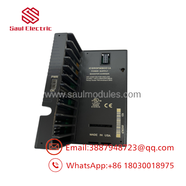
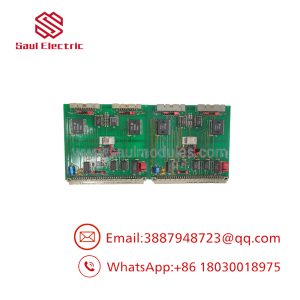
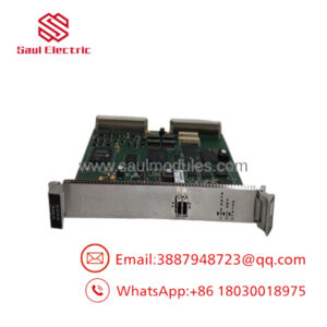
- IC200PWB001A
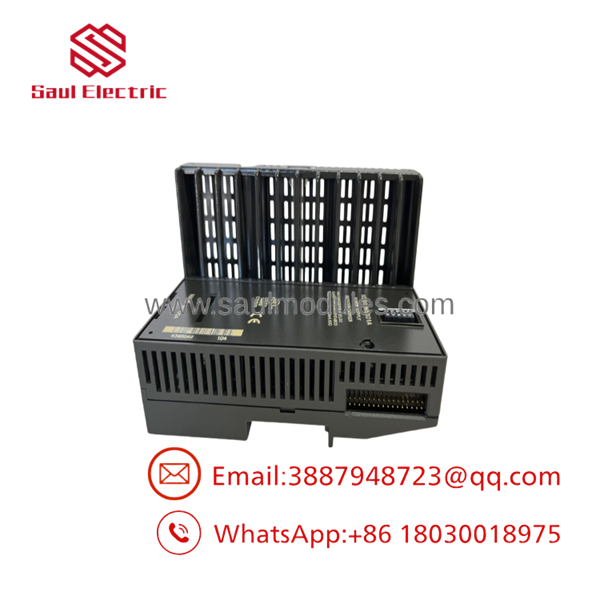
- IC200PWB001A
Transparency SOP: QA & Testing
To guarantee that our New Surplus and Remanufactured IC200PWB001A power supply modules deliver stable logic power under full load, each unit undergoes a 5-step bench test:
- Visual & Board Component Audit: Magnified inspection of the primary DC input terminals, connector pins, and internal capacitors for thermal stress or bulging.
- Wide Input Swing Test: Variable DC supply check sweeping input voltage from 18 VDC up to 30 VDC to verify smooth regulation on the output rails.
- Full 1.5A Load Bank Test: Connecting a 1.5A load bank to the 5 VDC output pins for 2 hours to measure voltage stability and ripple under maximum rated current.
- Hold-Up Time Verification: Simulating a 10 ms power interruption on the 24 VDC input line to confirm logic output remains steady without generating CPU fault flags.
- LED Diagnostic & Short Circuit Test: Momentarily shorting the 5V rail to verify that automatic current limiting triggers and the front panel “PWR” LED turns off safely.
The Veteran’s Tech Trap Guide
- ⚠️ Do Not Confuse Logic Power with Field Loop Power! The supplies 5 VDC / 3.3 VDC logic power to the backplane bus ONLY. It does NOT supply 24 VDC field loop power to drive output solenoids or 2-wire transmitters connected to adjacent I/O modules!
- PRO TIP: Calculate Your Total Backplane Current! Before adding extra I/O modules to a rack, sum up the 5 VDC backplane draw (mA) listed in each card’s specs. If your total exceeds the supply capacity of the main CPU or NIU, you must add an on a power booster carrier.
- ⚠️ Input Voltage Polarity: Double-check polarity when wiring +24 VDC and Ground to the input terminals. Wiring reversed DC polarity won’t blow the backplane, but it will trip internal fuses and keep the rack completely offline.
Dynamic FAQ
Q: Can the be used as a standalone power supply without a CPU or NIU? A: No. It is designed specifically as an snap-on power module that attaches directly to a VersaMax CPU, Network Interface Unit (NIU), or Power Expansion Booster Base (IC200PBI001).
Q: What is the difference between revision and later revisions like IC200PWB001B? A: Revision A is the original standard production release. Later revisions include minor component sourcing changes, but all revisions maintain identical form, fit, and 1.5A @ 5V performance specs.
Q: What does it mean when the front panel “PWR” LED is turned off? A: It indicates either that 24 VDC input power is missing/below 18 VDC, or an over-current/short-circuit condition on the backplane has tripped the module’s internal protection logic.
Q: Are these power supplies bench-tested and backed by a warranty? A: Yes. Every unit is tested under a full 1.5A thermal load and comes backed by a comprehensive 1-Year replacement warranty.

 Start Chat


