





Description
Key Technical Specifications
| Parameter | Value |
|---|---|
| Manufacturer | GE Fanuc |
| Model Number | IC660EPM100J |
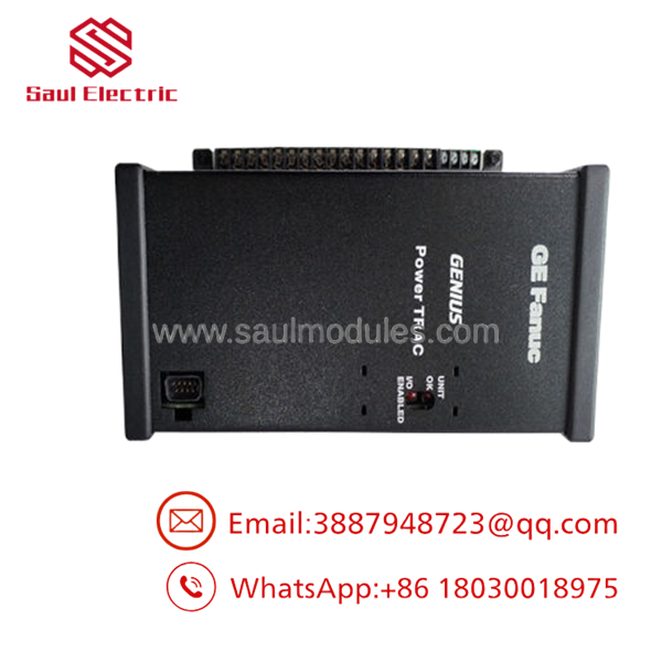
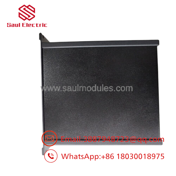
| Product Type | Genius PowerTRAC Electronic Assembly |
| Platform | GE Genius I/O |
| Companion Terminal Assembly | IC660TBM100 (sold separately) |
| Input Power | 115/230 V AC or 125 V DC |
| Power System Support | Single-phase and 3-phase |
| Measurements | Voltage, current, kW, kWh, RMS voltage, reactive power, power factor |
| Communication | Genius Bus |
| Configuration | Host PLC or Genius Hand-Held Monitor (HHM) |
| Update Rate | Approximately two updates per second |
| Operating Temperature | 32 °F to 140 °F (0 °C to 60 °C) |
Product Introduction
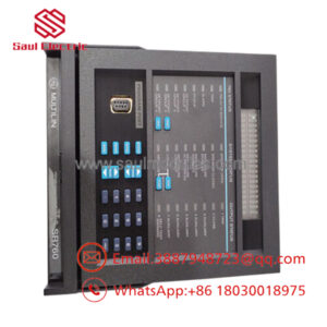
The GE IC660EPM100J is a Genius PowerTRAC Electronic Assembly designed for the GE Fanuc Genius I/O platform. It continuously measures voltage and current from instrument transformers, calculates electrical parameters such as kW, kWh, RMS voltage, reactive power, and power factor, and transmits the data to a host PLC or computer over the Genius Bus.
In power distribution, utility monitoring, and industrial energy management systems, this module provides real-time electrical measurements without requiring a separate power meter. Before replacing the unit, verify the Genius Bus configuration, terminal assembly compatibility, and instrument transformer ratios to avoid commissioning problems.
Troubleshooting Quick Reference
| Symptom | Possible Cause | Relevance to this Part | Quick Check Method | Recommendation |
|---|---|---|---|---|
| No status LEDs | Missing AC/DC supply | ❌ Low | Measure 115/230 V AC or 125 V DC input with a calibrated multimeter | Verify incoming power before replacing the module |
| PLC receives no power data | Genius Bus communication failure | ❌ Low | Check Genius Bus LEDs and network termination | Inspect bus wiring and node address |
| Incorrect kW or kWh values | Incorrect CT/PT ratio configuration | ✅ High | Compare configured transformer ratios with installed CTs/PTs | Correct configuration and retest |
| Voltage readings unstable | Loose PT wiring | ❌ Low | Measure PT secondary voltage and inspect terminals | Repair field wiring before replacing hardware |
| Current readings remain zero | Open CT secondary circuit | ❌ Low | Measure CT secondary current safely using approved procedures | Repair CT circuit immediately |
| HHM cannot communicate | Incorrect node address | ✅ Medium | Verify device address using the Genius HHM | Reconfigure the correct address |
| Module diagnostic fault | Internal electronics failure | ✅ High | Review diagnostics and LED indications | Replace the electronic assembly after confirming external circuits |
Technical Note: In the field, incorrect CT polarity, open CT circuits, PT wiring errors, or Genius Bus communication faults account for most service calls. The electronic assembly itself has a good reliability record. Verify external circuits before ordering a replacement.
- IC660EPM100J
- IC660EPM100J
Frequently Asked Questions (FAQ)
Q1. What is the IC660EPM100J used for?
It monitors electrical power systems by measuring voltage and current, then calculating energy and power parameters including kW, kWh, RMS voltage, reactive power, current, and power factor. The calculated values are transmitted to a host PLC through the Genius Bus.
Q2. Does this module support both single-phase and three-phase systems?
Yes.
The PowerTRAC module supports both single-phase and delta-configured three-phase electrical systems when connected to the appropriate current transformers (CTs) and potential transformers (PTs).
Q3. Is the terminal assembly included?
No.
IC660EPM100J is the electronic assembly only. It requires the compatible IC660TBM100 terminal assembly, which is supplied separately unless purchasing the complete block assembly.
Q4. Can I replace only the electronic assembly?
Yes.
One advantage of the Genius block design is that the electronic assembly can be removed while leaving the field wiring connected to the terminal assembly, reducing maintenance time. Always de-energize the system according to plant procedures before replacement.
Q5. Why is New Surplus inventory less expensive than factory inventory?
Most New Surplus units originate from canceled projects, OEM spare inventories, or unused maintenance stock. They have not been installed in production service but are no longer part of current factory production.
Q6. What should I verify before ordering?
Verify:
- Exact model number ()
- Terminal assembly (IC660TBM100)
- Genius Bus node address
- CT and PT ratios
- Supply voltage
- Firmware and configuration compatibility
Checking these items before purchase can eliminate many startup issues.
Q7. What warranty is typically available?
Most industrial automation suppliers offer a 12-month warranty on verified New Surplus or professionally tested units. Request a functional test report and photographs before shipment.
Quality Inspection & Testing SOP
1. Inbound Inspection & Traceability
- Verify GE Fanuc labels, serial numbers, and revision code.
- Inspect the enclosure for corrosion, cracks, scratches, UV discoloration, or evidence of previous repair.
- Verify connector integrity and terminal alignment.
- Record serial numbers for complete traceability.
2. Live Functional Testing
- Install the module on an in-house GE Genius I/O test network.
- Verify normal startup and LED operation.
- Simulate CT and PT inputs using calibrated sources.
- Confirm communication with a Genius Hand-Held Monitor (HHM) and host PLC.
- Verify calculated values for voltage, current, kW, kWh, and power factor.
- Perform a continuous 24-hour burn-in while monitoring operating temperature.
- Generate a documented functional test report.
- Test photos and videos are available upon request.
3. Electrical Parameter Testing
- Perform insulation resistance testing using a 500 V Megger where applicable.
- Verify protective ground continuity.
- Measure operating voltage and current using a calibrated Fluke 115 digital multimeter.
- Confirm stable measurements throughout the load test.
4. Firmware & Configuration Verification
- Record the installed firmware revision where applicable.
- Verify Genius Bus communication.
- Document node address and hardware revision before shipment.
5. Final QC & Packaging
- Final inspection and QC approval.
- Seal the unit in an ESD-safe bag.
- Package with anti-static foam, bubble wrap, and a heavy-duty corrugated carton.
- Apply a dated QC Passed label.
Technical Pitfalls & Survival Guide
❗ CT Polarity Is Easy to Get Wrong
I’ve seen perfectly healthy PowerTRAC modules replaced because one current transformer was installed backwards.
Verify CT polarity before assuming the module has failed.
❗ Never Leave a CT Secondary Open
This is more than a measurement issue.
An open CT secondary can generate dangerously high voltage and damage connected equipment. Always short the CT secondary before disconnecting the module when required by your maintenance procedure.
❗ Match the Transformer Ratios
The module only calculates correctly if the configured CT and PT ratios match the installed transformers.
Double-check these settings before commissioning.
❗ Verify the Genius Bus
Don’t blame the module immediately.
A loose bus connector, incorrect node address, or missing network termination can prevent data from reaching the PLC even when the PowerTRAC block is operating normally.
❗ Electrostatic Discharge (ESD)
Always wear a grounded wrist strap.
I’ve watched a replacement Genius module pass bench testing, then fail after installation because it was handled without ESD protection. Static damage often leaves no visible marks but can shorten the life of sensitive electronics.
Keep these checks in mind and you’ll eliminate most startup issues, avoid unnecessary module replacements, and reduce maintenance downtime.


 Start Chat


