





Description
Key Technical Specifications
| Parameter | Value |
|---|---|
| Module Type | DeviceNet Master (Scanner) Module |
| Supported Devices | Up to 63 DeviceNet slave nodes |
| Network Data Rates | 125 Kbps, 250 Kbps, 500 Kbps (Software or jumper configurable) |
| Bus Length Max | 500 m (1,640 ft) at 125 Kbps; 100 m (328 ft) at 500 Kbps |
| Backplane Current Draw | 450 mA at +5 V DC from the PLC backplane |
| Protocol Options | Master-Slave I/O polling, bit-strobe, change of state (COS), cyclic |
| Physical Connector | Standard 5-pin open terminal block (unsealed) |
| Operating Temperature | 0 to +60 °C (32 to 140 °F) |
Product Introduction
The GE Fanuc IC693DNM200-BD is a DeviceNet Master (Scanner) Module designed for the legacy Series 90-30 PLC platform. This module fits into any standard I/O slot of a 90-30 rack, serving as the network gateway that enables the central CPU to read and write to field-level industrial devices like motor drives, proximity sensors, valve manifolds, and remote I/O blocks over a single DeviceNet cable trunk.
The “-BD” suffix represents a field-hardened hardware revision that resolves historical CAN bus controller synchronization bugs found in earlier “AA” or “AB” iterations. Control engineers prioritize this module for brownfield modernization projects because it handles complex, multi-vendor networks natively, using standard Electronic Data Sheet (EDS) files to parse I/O profiles without introducing execution latency into the PLC’s core ladder logic loop.
Installation & Configuration Guide
Stage 1: Pre-Installation Preparation (Estimated Time: 20 minutes)
- ⚠️ Safety First: The IC693DNM200-BD runs communication lines for machinery networks. Extracting this module while the PLC is online will blind the controller to all remote field assets, causing an immediate safety shutdown or erratic machine behavior. Bring the process to a controlled halt. Shut off the main AC/DC power supplying the Series 90-30 PLC rack. Lock out and tag out the primary power disconnect switch.
- Tools Required: Grounded static-dissipative ESD wrist strap, small flathead screwdriver, and Proficy Machine Edition (PME) software setup with a valid serial or Ethernet programming link to the CPU.
- Data Backup: Connect your laptop to the CPU before killing power. Upload and save the complete PLC project file. Note down the DeviceNet scan list configuration, network baud rates, and target I/O memory assignments (%I, %Q, %AI, %AQ) tied to this module’s slot.
Stage 2: Removing the Old Module (Estimated Time: 5 minutes)
- Secure your ESD wrist strap and clip the lead to an unpainted metal grounding point on the rack frame.
- Unplug the 5-pin open DeviceNet terminal block connector from the faceplate of the module. Label the network drop trunk clearly.
- Locate the plastic release clips at the top and bottom of the old module housing.
- Press both clips firmly inward to disengage the mechanical hooks from the rack chassis.
- Pivot the module slightly upward and pull it straight out of the backplane slot guides.
- ⚠️ Note: Check the backplane connector socket inside the empty rack slot for any dust accumulations or bent terminal pins before continuing.
Stage 3: Installing the New Module (Estimated Time: 10 minutes)
- Maintain your ESD grounding connection. Remove the new surplus IC693DNM200-BD card from its anti-static shielding wrap.
- Verify that any physical hardware configuration switches on the side of the module match your original network baseline (such as fixed baud rate overrides).
- Insert the bottom hook of the module housing into the bottom slot alignment rail of the target rack space.
- Swing the top of the card inward toward the backplane connector. Press firmly until the top and bottom plastic release tabs snap locked into the rack channel.
- Reinsert the 5-pin DeviceNet network connector into the faceplate socket and tighten its small retaining screws.
- Self-Checklist:
- [ ] Module fully clicked home and mechanically locked at the top and bottom hooks.
- [ ] 5-pin network terminal block pinned out correctly and seated tight.
- [ ] Network trunk shield wire verified grounded at exactly one main distribution point.
Stage 4: Power-On & Testing (Estimated Time: 20 minutes)
- Reapply main power to the Series 90-30 PLC rack, and turn on the external 24 V DC power supply feeding the DeviceNet network cable.
- Monitor the front faceplate status lights. The MODULE OK LED should turn solid green after a brief internal diagnostic sequence.
- Open your PME software project and go to the hardware configuration layout for this slot. Verify that the card’s specific software revision properties match the “-BD” parameters.
- Download the original scan list configuration and register offsets to the PLC.
- Transition the PLC CPU into RUN mode. The NETWORK OK LED on the module should turn solid green, indicating that it has successfully initialized cyclic communication with all 63 downstream slave nodes on the bus.
- ⚠️ Troubleshooting Note: If the red COMM FAULT or ERROR light flashes, a node mismatch or network error is occurring. Verify that the DeviceNet 24 V DC bus power is alive and that the trunk line has exactly two 121 Ω terminating resistors installed across the blue and white data lines (one at each physical end of the network).
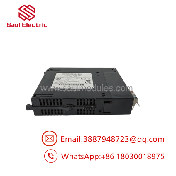
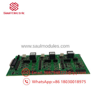
- IC693DNM200-BD
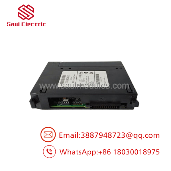
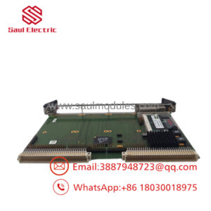
- IC693DNM200-BD
Frequently Asked Questions (FAQ)
Can I hot-swap the IC693DNM200-BD scanner while the rack power is active?
No. The Series 90-30 PLC backplane does not support hot-swapping of I/O or communication modules. Pulling the while the backplane has active voltage will cause electrical arcing across the data bus logic pins. This can permanently burn out the module’s transceiver chips, damage the master backplane rack tracks, and cause the main CPU to execute a fatal system watchdog halt, shutting down the entire PLC rack.
Why does this module require an external 24 V DC power source if it gets power from the backplane?
The card draws 450 mA of 5 V DC power from the PLC backplane purely to run its internal microprocessor, status LEDs, and backplane interface logic. However, the DeviceNet industrial protocol dictates that the physical network transceiver lines must be optically isolated and powered by an independent, external 24 V DC network supply. If you do not wire 24 V DC to the red and black terminals of the 5-pin faceplate plug, the module will remain completely deaf to network traffic.
What is the purpose of the 121 ohm resistors on a DeviceNet loop?
DeviceNet is built on the high-speed CAN bus standard, which is prone to signal reflections over long distances. To eliminate these reflections, you must install exactly two 121 Ω, 1/4-watt terminating resistors on the network. They must be wired directly across the white (CAN_H) and blue (CAN_L) signal lines at the two outermost physical ends of the network cable run. Omitting these resistors or adding too many will distort data packets, causing unpredictable network drops and CRC timeout errors.
Is the “-BD” revision compatible with a configuration built for an older “-AA” module?
Yes, the is backward-compatible and serves as a direct drop-in replacement for any older revision level of the IC693DNM200 family. The letter modifications indicate internal hardware upgrades designed to protect against CAN transceiver failures and improve noise filtering. You do not need to modify your PLC ladder code, though you may need to update the card’s revision level inside your PME hardware configuration project to match the hardware exactly before downloading.
How do I configure new field devices into this module’s scan list?
You cannot set up the DeviceNet scan list using standard PLC ladder logic blocks. You must use an engineering tool such as Proficy Machine Edition’s built-in DeviceNet configuration utility or an external CAN configuration tool. This software reads the Electronic Data Sheet (.EDS) files provided by the field device manufacturers, sets up the polling frequencies, maps the device data into the %I and %Q memory registers of the 90-30 CPU, and writes this master map directly into the non-volatile flash memory of the card.

 Start Chat


