





Description
Product Introduction & Engineering Value
When one PLC output module must operate both AC and DC field devices, transistor outputs quickly reach their limits. Relay outputs remain the preferred choice whenever electrical isolation, voltage flexibility, and compatibility with mixed loads are required.
The GE IC693MDL930 is an 8-point isolated relay output module designed for the Series 90-30 PLC platform. Every output uses an independent Form A (Normally Open) relay contact capable of switching either AC or DC loads. Because each channel is electrically isolated, the module can simultaneously control different voltage circuits without shared commons.
Technical Specifications
| Parameter | Specification |
|---|---|
| Manufacturer | GE Fanuc (Emerson) |
| Model | IC693MDL930 |
| Product Family | Series 90-30 |
| Module Type | Isolated Relay Output Module |
| Output Channels | 8 individually isolated outputs |
| Contact Type | Form A (Normally Open) Relay |
| Rated Voltage | 24 VDC, 120/240 VAC |
| Operating Voltage | 5–30 VDC or 5–250 VAC, 50/60 Hz |
| Maximum Resistive Load | 4 A per output |
| Pilot Duty Rating | 2 A per output |
| Maximum Module Load | 20 A (UL installations) |
| Minimum Load | 10 mA |
| Maximum Inrush Current | 5 A |
| ON Response Time | 15 ms maximum |
| OFF Response Time | 15 ms maximum |
| Isolation | 1500 VAC field-to-backplane; 1500 VAC point-to-point (1 minute test) |
| Backplane Current | 6 mA @ 5 VDC bus; 70 mA @ 24 V relay bus |
| Status Indicators | One LED per output channel |
| Installation | Compatible with any Series 90-30 I/O slot |
Field Application & The “Trench” Experience
A municipal water treatment facility was modernizing several pump control panels. The PLC needed to operate 24 VDC alarm beacons, 120 VAC motor starter coils, and a handful of legacy 240 VAC solenoid valves. Rewiring everything to a common voltage would have extended the shutdown by several days.
The maintenance team installed an IC693MDL930, assigning each isolated relay output to its respective voltage circuit. Since every relay has its own common terminal, the existing field wiring remained largely unchanged. Startup was completed during a scheduled outage, and the mixed-voltage control scheme continued operating without additional interposing relays.
Typical applications include:
- Pump station motor starter control
- Boiler burner permissive and alarm circuits
- Packaging equipment with mixed AC/DC actuators
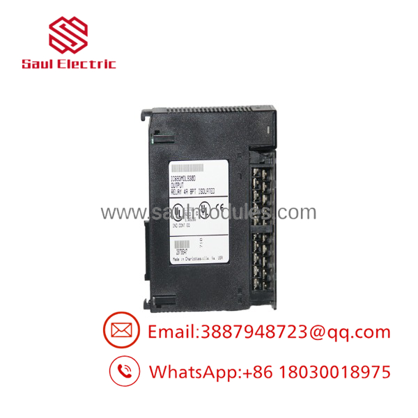
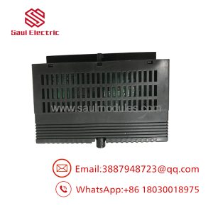
IC693MDL930
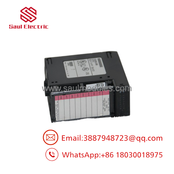
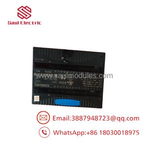
IC693MDL930
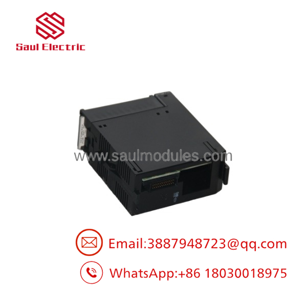
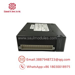
IC693MDL930
Transparency SOP: QA & Testing
Every IC693MDL930 undergoes a documented inspection before shipment.
- Verify part number, hardware revision, and relay identification.
- Inspect relay contacts, screw terminals, housing, and backplane connector.
- Install the module in a Series 90-30 test rack.
- Energize each relay individually using both AC and DC test loads.
- Measure contact switching, response time, and LED indication.
- Perform repeated switching cycles to verify relay operation under load.
- Package the module using ESD-safe materials and protective industrial packaging.
New Surplus modules are visually inspected to verify unused OEM condition. Refurbished units complete additional relay endurance and functional load testing before release.
The Veteran’s Tech Trap Guide
⚠️ There Are No Built-In Output Fuses
The IC693MDL930 does not include internal fuse protection. External branch circuit protection should always be provided based on the connected load and applicable electrical standards.
⚠️ Respect the Total Module Current
Although each relay is rated for 4 A resistive, the complete module is limited to 20 A total in UL installations. It’s easy to exceed the overall rating when several outputs drive heavy loads simultaneously.
PRO TIP: Install surge suppressors directly across inductive loads such as contactors and solenoids. Suppressing the voltage spike significantly extends relay contact life and reduces electrical noise.
⚠️ Remember the Relay Response Time
Relay outputs require approximately 15 ms to energize and de-energize. They are well suited for machine control but should not be used for high-speed pulse generation or motion control applications.
Dynamic FAQ
Q1. What makes the IC693MDL930 different from a transistor output module?
The uses electromechanical relay contacts, allowing it to switch both AC and DC loads over a wide voltage range, unlike transistor outputs that are generally limited to DC applications.
Q2. Can each output switch a different voltage?
Yes. Every relay output is individually isolated and has its own common terminal, allowing one channel to switch 24 VDC while another switches 120 VAC or 240 VAC.
Q3. What loads are commonly controlled by this module?
Typical applications include motor starters, interposing relays, solenoid valves, indicator lamps, alarm beacons, and contactor coils operating on either AC or DC power.
Q4. Is the suitable for high-speed switching?
No. With a 15 ms ON/OFF response time, it is intended for standard industrial control rather than pulse-width modulation, encoder simulation, or other high-speed switching tasks.
Q5. Can this module be installed in any Series 90-30 rack?
Yes. The occupies a single I/O slot and can be installed in any compatible Series 90-30 baseplate with sufficient backplane power available.
Q6. How are New Surplus and Refurbished modules verified?
Every module undergoes identification verification, connector inspection, relay switching tests, LED diagnostics, load verification, and repeated operational testing. Refurbished units additionally complete extended relay cycling and burn-in testing before shipment.

 Start Chat


