





Description
Product Introduction
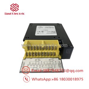
The GE Fanuc IC693MDL940 is a 16-point 2 Amp Relay Output Module engineered for GE Series 90-30 PLC systems. Occupying a single option slot on any CPU, expansion, or remote baseplate, it provides dry-contact mechanical switching (Normally Open / Form A) to control high-power or mixed-voltage field loads directly from the PLC backplane without needing intermediate interposing relays.
Organized into four isolated groups of 4 points (Groups A, B, C, and D), each group features its own dedicated common line, enabling flexible mixed-voltage operation (e.g., controlling 120VAC solenoids on Group A while switching 24VDC control circuits on Group B). High dielectric isolation shields backplane microprocessors, while the hinged door houses a 16-LED status grid for visual diagnostic verification.
Key Technical Specifications
| Parameter | Specification |
| Full Part Number | IC693MDL940 (Covers all revision levels) |
| Module Type | Discrete Relay Output (Normally Open / Form A) |
| Number of Points | 16 Points (4 isolated groups of 4 points: A, B, C, D) |
| Operating Voltage Range | 5 to 30 VDC or 5 to 250 VAC (47–63 Hz) |
| Current Rating per Point | 2.0 A maximum continuous per point (Resistive / Pilot Duty) |
| Group / Module Limits | 4.0 A max per common/group; 16.0 A max total per module |
| Minimum Load Current | 10 mA at 5 VDC |
| Contact Response Time | 15 ms maximum ON delay / 15 ms maximum OFF delay |
| Backplane Current Draw | 7 mA at 5 VDC; 135 mA at 24 VDC Relay Bus (from rack supply) |
| Isolation | 1500V RMS between field side and backplane; 500V RMS between groups |
| Terminal Block | 20-terminal removable terminal connector block |
Application Scenarios & The “Trench” Experience
At 3:45 AM during a critical batch cycle at a wastewater treatment plant, a secondary aeration pump contactor failed to pull in. The CPU output bit was forced ON, but point 2 on the module showed no continuity across the field terminals—years of high-cycle inductive arcing from an unsuppressed motor starter coil had welded the mechanical relay contacts open. With the aeration tank unoxygenated, biological treatment parameters were rapidly slipping out of compliance, risking a plant shutdown.
Application Scenarios
- Mixed-Voltage Control Cabinets: Simultaneously switches 120VAC pilot lights, 24VDC solenoid valves, and 240VAC motor contactors from a single module slot.
- Motor Starter & Contactor Actuation: Drives NEMA size 0 through 4 starter coils directly without external interposing relay bases.
- Facility Utility Management: Controls exhaust fans, louvers, lighting contactors, and unit heater interlocks.
- Safety & Alarm Systems: Provides dry-contact closure outputs for master building management systems (BMS), security panels, and emergency horns.
Field Case Study
A glass manufacturing facility in Ohio suffered a sudden shutdown on their main furnace exhaust damper control system when a voltage surge pitted contacts on multiple channels of their legacy IC693MDL940 module. The damper stood frozen, accumulating heat and risking refractory lining damage. We dispatched a bench-tested, pre-cleared surplus IC693MDL940 card via local hot-shot courier. The site electrician killed rack power, swung the wired 20-pin terminal block over to the new card, slid the card into option slot 2, and had the furnace ventilation damper system operational within 15 minutes of delivery.
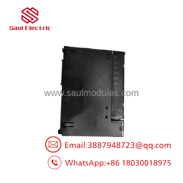
IC693MDL940
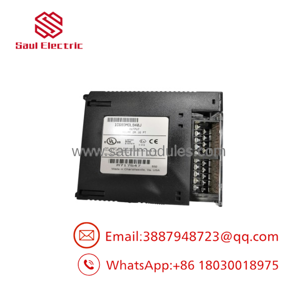
IC693MDL940
Transparency SOP: Quality Assurance & Testing
We test every IC693MDL940 unit under live mechanical load on active GE test racks before adding it to our ready-to-ship inventory.
- Inbound Visual Verification: Inspection for casing cracks, bent backplane pins, contact wear marks, terminal block latch integrity, and OEM tag authenticity.
- Backplane Power-On Check: Slotted into an active GE Series 90-30 rack (IC693CHS392 driven by an IC693PWR330 supply) to verify 24VDC relay bus coil supply initialization and logic communication.
- 16-Point Contact Resistance & Load Test: Cycled all 16 Form-A mechanical relays individually under a 120VAC / 2A resistive load while measuring closed-contact resistance (<0.2 ohms) and checking LED response.
- Thermal Soak & Stress Test: Subjected to continuous 1-Hz contact switching under full load for 4 hours inside a thermal chamber to ensure zero contact bounce or mechanical coil degradation.
- ESD Sealing & Final QC: Terminals inspected, card cleaned, and sealed inside heavy-duty ESD shielding with custom impact-resistant protective packaging.
The Veteran’s Tech Trap Guide
- ⚠️ Utilize the Removable Terminal Block: You do not need to unscrew field wiring when replacing a failed IC693MDL940! The module features a 20-terminal removable connector block. Simply loosen the top/bottom retaining screws, pop off the wired terminal block, swap the card, and snap the block onto the replacement unit.
- ❗ Never Hot-Swap on the Baseplate: The GE Series 90-30 backplane is not hot-swappable! Inserting or pulling the while the baseplate power supply is energized can arc backplane pins, ruin internal backplane transceivers, or trigger a CPU hardware fault. Always kill main rack power first.
- ⚠️ Install RC Snubbers / MOV Suppression: Because these are mechanical dry contacts, switching inductive loads (solenoid coils, relay coils, magnetic brakes) causes arcing that erodes contact tips. Always install an RC snubber or Varistor (MOV) across AC inductive loads, or a flyback diode across DC inductive loads, to extend contact life.
- ❗ Watch Out for Minimum Load Current (10 mA): Mechanical relay contacts need a minimum wetting current (~10 mA at 5 VDC) to punch through oxidation films on the contacts. Using an to switch ultra-low micro-amp signals (like high-impedance instrumentation inputs) can lead to intermittent open-circuit readings over time.
Frequently Asked Questions (FAQ for Conversion)
Q: Is the GE Fanuc hot-swappable?
A: No. You must turn off main power to the Series 90-30 baseplate before removing or installing the module to prevent backplane or chip damage.
Q: What is the difference between solid-state output modules (like IC693MDL741) and the ?
A: Solid-state modules use transistors (DC only) or triacs (AC only) for high-speed, non-wearing switching. The uses physical mechanical relays, meaning it can switch both AC and DC currents up to 2A, but has a finite mechanical lifespan.
Q: Can I switch different voltages on different groups of the same card?
A: Yes! The 16 points are divided into 4 isolated groups of 4 points (A, B, C, D), each with its own isolated common terminal. You can run 120VAC on Group A, 24VDC on Group B, and 240VAC on Group C simultaneously.
Q: Do I need to re-program the PLC when replacing an ?
A: No. As long as the replacement unit matches the model number and is installed in the same option slot, no software reconfiguration or ladder logic editing is required.
Q: What warranty coverage comes with this surplus relay card?
A: Every module comes backed by a full 12-month replacement warranty. All units are authentic GE Fanuc surplus equipment, thoroughly inspected, cleaned, and bench-tested under live 2A load cycles prior to shipping.

 Start Chat


