





Description
Key Technical Specifications
| Parameter | Value |
| Microprocessor Type | Intel Celeron M running at 1 GHz internal clock speed |
| User Logic/Data Memory | 64 MB volatile battery-backed RAM |
| Non-Volatile Internal Storage | 64 MB flash memory partition |
| Redundancy Capabilities | Supports hot-standby CPU pairing with bumpless transfer (\le 1 scan cycle) |
| Integrated Communication Layout | 1 x RS-232 (RJ-11), 1 x isolated RS-485 (15-pin D-sub) |
| Supported System Protocols | Modbus RTU Slave, SNP, Serial I/O, Modbus Master (via logic blocks) |
| Environmental Protection | Factory conformal coated PCB layers for harsh/corrosive atmospheres |
| Total Discrete I/O Capacity | 32,768 Inputs (%I) and 32,768 Outputs (%Q) max boundaries |
| Total Analog I/O Capacity | 32,768 Inputs (%AI) and 32,768 Outputs (%AQ) max boundaries |
| Backplane Current Load | 1.25 A at 5 V DC; 1.0 A at 3.3 V DC backplane rails |
Product Introduction
The GE IC695CRU320-EZ is a high-performance 1 GHz Intel Celeron M redundancy Central Processing Unit engineered for the PACSystems RX3i Universal Controller platform. Featuring an expanded 64 MB user memory capacity and a factory-applied conformal coating, this specialized processor is built to manage complex, calculation-heavy automation strategies in critical environments such as water treatment systems, chemicals production, and thermal power facilities.
The “CRU” designator signifies native support for dual-rack, hot-standby configuration topologies. When coupled via dedicated high-speed fiber-optic synchronization modules (like the IC695RMX128), two IC695CRU320-EZ units continuously mirror process variables and data tables. In the event of a primary controller failure, the backup processor takes over within a single scan cycle, executing a bumpless transfer that prevents field disruptions or process downtime.
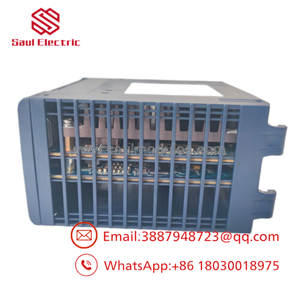
- IC695CRU320-EZ
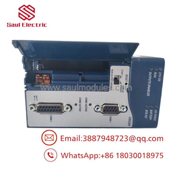
- IC695CRU320-EZ
Installation & Configuration Guide
Stage 1: Pre-Installation Preparation (Estimated Time: 20 minutes)
- ⚠️ Safety First: De-energize and lock out the primary AC or DC power line feeding the specific RX3i universal rack slot target. Working on a live PCI backplane layout risks creating a hardware tracking error or blowing out internal communication logic chips across neighboring I/O cards.
- Tools Required: Grounded static-dissipative ESD wrist strap, clean anti-static field surface mat, and an engineering laptop with Proficy Machine Edition V5.60 or later.
- Data Backup: Connect your computer to the operational primary CPU. Upload and archive a complete image copy of the active project file, including hardware properties, register variables (%R), and target configuration maps.
Stage 2: Removing the Faulty CPU (Estimated Time: 5 minutes)
- Clamp your ESD wrist strap directly to a bare-metal grounding point on the enclosure frame chassis.
- Label and disconnect any serial line connections running into the front-panel RJ-11 or 15-pin D-sub ports.
- Completely back out the upper and lower faceplate retaining screws securing the module housing to the rack frame.
- Firmly pinch the integrated top and bottom plastic extraction handles to release the internal latch hooks.
- ⚠️ Note: Pull the module straight out along the guide rails to prevent twisting or scratching the multi-pin PCI backplane connector interface. Place the module inside a static-shielding bag.
Stage 3: Installing the New Redundancy CPU (Estimated Time: 15 minutes)
- Remove the new IC695CRU320-EZ module from its original static wrap, handling it by the faceplate plastic housing.
- Verify that the hardware identification and suffix matches your system configuration specs (e.g., matching the “-EZ” suffix indicates a conformal coated model).
- Align the circuit board edge with the top and bottom guide slots of the designated slot path (typically Slot 1 or 2 in a universal backplane layout).
- Slide the card smoothly rearward until it contacts the backplane receptacle. Apply firm, even horizontal pressure on the top and bottom faceplate corners until the module is fully seated and the handles latch.
- Tighten the upper and lower retaining screws to secure the chassis ground path.
Stage 4: Power-On & Redundancy Synchronization (Estimated Time: 20 minutes)
- Re-apply input power to the universal backplane chassis rack.
- Watch the front-panel status LED progression. The PWR and OK LEDs must light up solid green. If the FAULT indicator lights up or flashes red, access the diagnostic buffer to review internal power-on self-test errors.
- Connect your laptop using an RJ-11 serial line or over an adjacent Ethernet network module link.
- Launch Proficy Machine Edition, establish an online connection, and clear any residual memory profiles on the new CPU.
- Download your archived project logic configuration. Set the redundancy parameters to designate the rack as either the Primary or Secondary node as required by your site architecture.
- Toggle the running state to RUN mode. Check that the synchronization indicators on your fiber link modules confirm an active, locked hot-standby state.
- ⚠️ Troubleshooting Note: If the backup rack fails to sync or throws a hardware mismatch alert, verify that the firmware versions on both the primary and secondary IC695CRU320-EZ modules match exactly. Redundant configurations require identical firmware baselines to mirror memory structures.
Frequently Asked Questions (FAQ)
What does the “-EZ” suffix on this part number represent?
The -EZ suffix indicates that the module features a factory-applied conformal coating on its internal printed circuit board layers. This protective coating seals the electronic components against ambient moisture, conductive dust particles, and corrosive gases (like hydrogen sulfide) typically found in wastewater treatment facilities, chemical processing areas, and pulp and paper mills.
Can I mix an with a standard non-coated IC695CPU320 in a redundant system?
Technically, they share the same internal processor architecture and memory layout, but mixing them in a live redundant pair is highly discouraged. For reliable bumpless hot-standby synchronization, both the primary and backup racks should use identical hardware profiles. Furthermore, using a non-conformal coated module in an aggressive environment will compromise the high-availability goals of your system.
Do I need a separate backup battery to prevent program loss on this card?
Yes. The 64 MB execution memory layer uses volatile RAM to maintain rapid logic execution loop tracking. To prevent program loss during a power outage, you should connect a standard GE/Emerson lithium smart battery pack to the designated port header behind the front door. To add an extra layer of protection against code loss, you can burn your final compiled logic directly into the 64 MB non-volatile flash partition using your programming utility.
How fast does the system execute a switchover if the primary CPU fails?
When integrated with matching IC695RMX128 fiber-optic synchronization cards, the system performs a bumpless transfer within a single scan cycle (typically under 5 to 10 milliseconds, depending on your overall program scope). The backup controller assumes full ownership of the localized I/O image tables and active network pathways without interrupting field devices, valve lines, or critical safety loops.
Since Emerson now supports the PACSystems line, what is the availability of this specific module?
This hardware component is available as New Original / New Surplus stock sourced from clean, climate-controlled spare parts reserves, distribution overstock, and canceled modernization projects. While Emerson has advanced the PACSystems line with newer controller architectures, the CRU320-EZ remains a critical component for facilities running legacy dual-rack setups. We perform comprehensive backplane communication checks and memory verification diagnostics to guarantee out-of-box reliability, and we back this module with a full 1-year operational warranty.



 Start Chat


