





Description
Key Technical Specifications
| Parameter | Value |
| Processor Type | Intel Pentium M (1.2 GHz) |
| User Memory | 64 MB Battery-Backed RAM |
| Non-Volatile Flash Memory | 64 MB for user program and data storage |
| Embedded Ethernet | 3 Ports (One 10/100/1000 Mbps RJ45, two 10/100 Mbps RJ45) |
| Serial Communications | 1 RS-232 port (Station manager), 1 RS-485 port |
| VME64 Backplane Support | Compiles with VME64 Standard C.1 |
| Current Consumption | 5.5 A at +5 V DC, 0.5 A at +12 V DC |
| Operating Temperature | 0 to +60 °C (32 to 140 °F) with forced air cooling |
Product Introduction
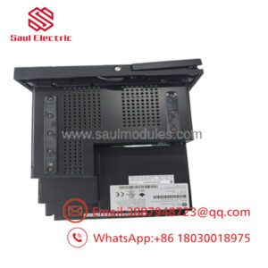
The GE PACSystems RX7i IC698CPE020-JX is a high-performance CPU module engineered for complex, large-scale industrial control applications. Built on a standard VME64 backplane architecture, this controller combines the speed of an embedded 1.2 GHz Intel processor with a robust real-time operating system. It provides the high-capacity throughput required for advanced motion control, process control, and high-availability redundant systems.
The “-JX” suffix designates a specific manufacturing revision that optimizes the onboard flash memory interface and firmware handling. Plant engineers select this particular CPU model for its native triple-port Ethernet connectivity, which isolates control networks from plant-wide business networks without adding separate communication modules. Its dual-backplane processing capability enables direct control of both legacy Series 90-70 I/O and modern RX7i high-speed modules.

- IC698CPE020-JX
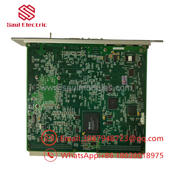
- IC698CPE020-JX
Installation & Configuration Guide
Stage 1: Pre-Installation Preparation (Estimated Time: 20 minutes)
- ⚠️ Safety First: Modifying a main system CPU requires a complete plant or line shutdown. Ensure the managed process is brought to a verified safe state. Turn off all AC/DC power supplying the RX7i rack. Lock out and tag out the main breaker. Wait 5 minutes for backplane capacitors to discharge.
- Tools Required: Grounding wrist strap, small flat-head screwdriver, Machine Edition programming software (PME V5.5 or later), Ethernet crossover cable or standard patch cable.
- Data Backup: Connect to the existing controller using PME. Perform a complete upload of the logic project, hardware configuration, and variables. Document the exact IP address subnet mask, gateway, and serial port settings.
Stage 2: Removing the Old Module (Estimated Time: 5 minutes)
- Attach your ESD wrist strap to the rack chassis ground.
- Disconnect all Ethernet and serial cables from the faceplate of the old CPU. Label each cable to ensure correct port mapping during reassembly.
- Loosen the upper and lower retaining screws on the CPU module front panel.
- Grasp the injector/ejector tabs at the top and bottom of the card. Pull them outward simultaneously to unseat the module from the VME backplane pins.
- Slide the module straight out of the slot guide rails.
- ⚠️ Note: Do not touch the backplane connector pins or circuit components. Keep the old CPU nearby to verify its exact hardware hardware switch states.
Stage 3: Installing the New Module (Estimated Time: 15 minutes)
- Maintain your ESD grounding connection. Remove the new IC698CPE020-JX from its protective shielding bag.
- Locate the memory backup battery on the CPU board. Connect the battery lead wire to the onboard terminal connector if it was shipped uncoupled.
- Check the hardware toggle switches on the module faceplate (Run/Stop, Outputs Pack, Memory Protect). Match their initial positions to the old CPU requirements.
- Align the CPU circuit board with the top and bottom guide rails of Slot 1 in the RX7i rack (Slot 1 is mandatory for the system master controller).
- Slide the card into the slot until the injector/ejector handles touch the rack frame. Press the handles inward to lock the module pins into the backplane.
- Tighten the top and bottom retaining screws to secure the faceplate to the rack frame. Reattach the communication cables.
- Self-Checklist:
- [ ] Module fully seated in Slot 1 and handles locked inward.
- [ ] Onboard battery connected securely.
- [ ] All communications cables reconnected to their original designated ports.
Stage 4: Power-On & Testing (Estimated Time: 25 minutes)
- Apply power to the RX7i rack. Watch the front-panel status LEDs.
- The OK LED should flash during boot diagnostics and then remain solid green. The RUN and OUTPUTS LEDs will remain off until code is loaded.
- Connect your programming PC to the CPU’s dedicated Ethernet port or Station Manager serial port.
- Ping the default or configured IP address to confirm physical network connection.
- Open your PME project. Verify that the hardware configuration matches the “JX” revision firmware parameters. Download the backed-up logic project and hardware configuration.
- Toggle the physical run switch to the RUN position or initiate it via the software. Confirm the RUN and OUTPUTS LEDs turn solid green.
- ⚠️ Troubleshooting Note: If the OK LED flashes continuously or stays amber, an internal diagnostic fault or firmware mismatch exists. Connect through the Station Manager port to read the CPU fault table logs for exact error definitions.
Frequently Asked Questions (FAQ)
Is this model hot-swappable in the RX7i rack?
No. The PACSystems RX7i backplane does not support hot-swapping for the main CPU module. Removing or inserting the IC698CPE020-JX while the backplane power is active will cause an electrical arc across the VME pins. This can fry the processing unit, damage the backplane bus traces, and cause immediate corruption of running memory across any adjacent I/O modules. Always turn off power to the entire rack before servicing.
My original part is an IC698CPE020 without the “-JX” suffix. Are they compatible?
Yes, the -JX is a direct form, fit, and function replacement for the older base modules. The “-JX” extension signifies an internal engineering hardware modification, often updating components that reached end-of-life status. However, when migrating to the “-JX” revision, you must verify your Machine Edition software version and check that your current project’s hardware configuration allows the matching firmware revision level.
Will the CPU retain its logic program if the rack loses power?
The -JX utilizes a dual-layered backup strategy. It contains internal battery-backed RAM to preserve volatile user programs, fault tables, and variable registers during short-term power losses. Additionally, it has 64 MB of non-volatile flash memory. To ensure your logic is safe during long-term storage or battery failure, always execute the “Write to Flash” command inside your programming software after compiling your final code updates.
What should I do if the “BATTERY” LED turns red on the faceplate?
A red BATTERY LED indicates that the onboard lithium cell voltage has dropped below the safe threshold required to maintain the user memory during a power cycle. If the rack remains powered up, your program is safe. However, if the rack is powered down while this light is on, the RAM contents will be lost. Replace the battery pack immediately while the rack power is turned ON to avoid losing your active program.
Why does this module require forced air cooling?
The 1.2 GHz Pentium M processor generates substantial thermal energy during full logic and communication processing. The RX7i rack architecture relies on forced ventilation from an external fan tray assembly mounted beneath the card cage. If your cabinet fan filters are blocked or the fan tray fails, the CPU will heat up rapidly and execute an automatic thermal shutdown to prevent physical circuit damage, causing an unplanned turbine or process trip. Always inspect air filters during routine maintenance.

 Start Chat


