





Description
Key Technical Specifications
| Parameter | Value / Specification |
| System Compatibility | GE Mark VI Speedtronic Innovation Series Excitation |
| Board Typology | Exciter Power Monitor Card (EPMC) |
| Form Factor | High-density multi-layer PCB mounted on plate assembly |
| Inputs | Three-phase bridge AC voltage sensing, bridge shunt current feedback |
| Outputs | Gate pulse drive signals to SCRs, thermal sensor excitation |
| Pulse Width Modulation (PWM) | Handled via upstream UCVE/UCCA controller interface |
| Diagnostic Capabilities | Overcurrent, bridge phase loss, thyristor short-circuit tracking |
| Isolation Rating | High-voltage galvanic isolation between power electronics and control logic |
| Cooling | Convection via rack/cabinet airflow dynamics |
| Operating Humidity | 5 to 95% non-condensing relative humidity |
Product Introduction
The GE IS200EPMCH1 functions as a critical bridge interface card within the Mark VI Speedtronic Excitation Control System. It bridges the gap between low-voltage digital control processors and the high-power Silicon Controlled Rectifier (SCR) bridges that feed the generator rotor field windings. The module manages gate drive pulse routing while continuously sampling voltage, line current, and thermal telemetry directly from the active power bridge.
Operating with high galvanic isolation, the IS200EPMCH1 protects delicate control networks from lethal high-voltage field transients. It provides millisecond-level feedback loops to the central Mark VI controller, ensuring that any single-phase drop, fuse clearing, or individual SCR short-circuit is caught before a minor commutation imbalance cascades into a total generator trip.
Installation & Configuration Guide
Stage 1: Pre-Installation Preparation (Estimated Time: 15 minutes)
- ⚠️ Safety First: Lock out and tag out (LOTO) both the control power supply and the main generator field excitation input breakers. High-voltage DC field energy and 3-phase AC voltage lines are present near this card’s terminal pathways. Wait 10 minutes to allow any inline snubber capacitors to fully discharge down to 0 V. Verify with a calibrated multimeter before proceeding.
- Tools Required: Grounded static wrist strap, magnetic M4/M5 nut driver, Philips PH2 screwdriver, insulation tester (Megger), smartphone for referencing physical configurations.
- Data Backup: Ensure you have access to the current Toolbox software project files for the specific Mark VI turbine profile. Take clear macro photos of all factory hardware jumpers, wire connections, and shield grounding bars on the existing board.
Stage 2: Removing the Old Module (Estimated Time: 10 minutes)
- Affix your ESD strap to a clean metal frame point on the cabinet housing.
- Label each ribbon cable, fiber-optic link (if present on your revision), and discrete copper plug tied to the board edges.
- Loosen the retention screws on the high-current plug connectors and gently unplug them. Do not tug on the wiring looms.
- Unscrew the mounting plate assembly fasteners holding the EPMC board to the internal cabinet rails.
- Pull the board straight forward to clear any backplane standoffs. Place it inside a protective static shielding sleeve.
Stage 3: Installing the New Module (Estimated Time: 15 minutes)
- Unpack the replacement IS200EPMCH1 module on a static-safe work surface.
- Configuration Clone: Locate all configuration hardware jumpers on both the old card and the new card. Replicate the precise positions of every jumper header to match the old card’s layout, paying attention to any scaling or attenuation resistors influenced by jumper states.
- Position the new plate assembly against the chassis rails, starting the mounting bolts by hand to avoid cross-threading. Tighten them to factory torque specifications.
- Reattach all logic ribbon cables and high-power harness connectors, seating them fully until the locking mechanisms click or lock down tightly.
Stage 4: Power-On & Testing (Estimated Time: 20 minutes)
- Perform a point-to-point resistance check from the board ground plane to the main enclosure grounding bus bar to confirm continuity.
- Close the low-voltage control power breaker only. Leave the high-power excitation bridge breaker open.
- Observe the diagnostic status lights on the EPMC card and the matching diagnostic fault register inside the Toolbox configuration suite.
- If the board returns a healthy startup handshake with zero fault messages, proceed to clear the turbine area, close the high-voltage excitation supply lines, and begin standard diagnostic startup testing sequences according to plant OEM field procedures.
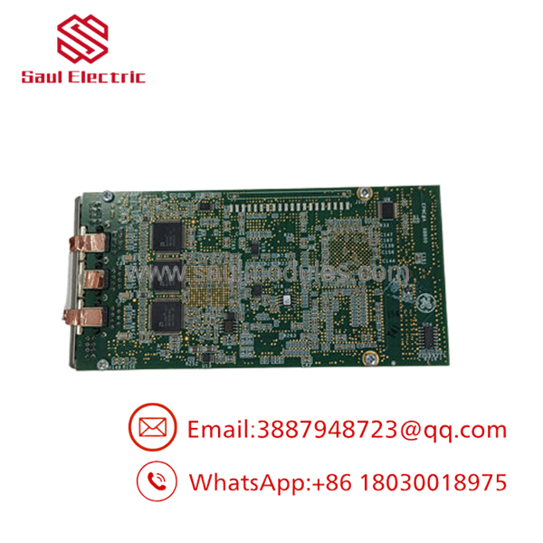
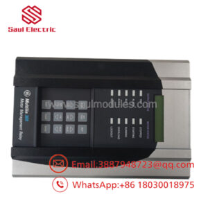
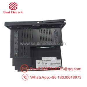
- IS200EPMCH1
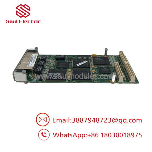
- IS200EPMCH1
Frequently Asked Questions (FAQ)
Can I hot-swap this module during active generator operation?
Absolutely not. Pulling an IS200EPMCH1 board while the generator is running breaks the gate drive circuit loop to the SCR power bridge. Doing so can cause unstable field conditions, immediate cross-conduction, blown high-speed semiconductor fuses, or catastrophic destruction of the main rotor windings. Only attempt to replace this module during a complete unit outage with all excitation power sources locked out.
What is the functional difference between an H1A and H1B suffix on this card?
The alphanumeric suffix at the end of the GE part number represents minor backward-compatible hardware design iterations, such as updated component packaging or upgraded trace insulation properties. In nearly all standard Mark VI excitation applications, an H1B module can directly substitute an older H1A card, provided that you carefully match all hardware jumper configurations and verify that your system’s current Toolbox configuration project recognizes the physical layout.
Does this board require independent firmware flashing prior to installation?
No, the is primarily an analog-and-digital hardware interface layer. It functions by routing and processing signals under the management of the master Mark VI core processor card (such as a UCVE or UCCA board). As long as your master controller contains the proper hardware profile and configuration parameters, this board will run out of the box once the physical jumpers are correctly mirrored.
Why do some surplus boards arrive with a different mounting plate design?
GE produced several form-factor configurations of the EPMC platform to fit distinct enclosure depths and cooling array variations inside their heavy-duty Innovation Series cabinets. If the internal PCB designators and model code match (“IS200EPMC”), you can transfer the electronic board directly to your original plate assembly if the new plate frame exhibits physical alignment conflicts inside your specific rack chassis.
How do I diagnose an instant “Bridge Fault” immediately following a swap?
If a fault triggers right after powering up a new board, it usually points to a misaligned configuration jumper or a dirty ribbon cable seating. Power down the system, unseat the primary communication cables, verify there is no dust or debris in the connector pins, double-check your macro photos to confirm the jumper headers match exactly, and reseat everything securely.

 Start Chat


