





Description
Key Technical Specifications
| Parameter | Value |
| Manufacturer | General Electric (GE) |
| Part Number | IS200ESYSH1AAA |
| Board Acronym | ESYS |
| Revision Level | H1AAA (Group 1, Initial Artwork Generation) |
| System Architecture | Triple Modular Redundant (TMR) or Single Configuration |
| Interface Connections | High-speed internal serial links, multi-pin backplane connectors |
| Application Environment | EX2100e Excitation Systems / Mark VIe Turbine Control |
| Power Consumption | Sourced via internal rack backplane from EPSM module |
| Isolation Rating | Galvanic high-frequency signal noise isolation |
| Operating Temperature | −30 to +65°C |
| Form Factor | Double-height, single-slot industrial rack card |
Product Introduction
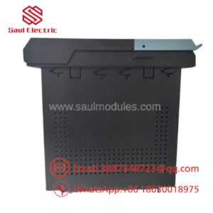
The GE IS200ESYSH1AAA is a high-speed serial System I/O board designed exclusively for the EX2100e excitation system and Mark VIe turbine control platforms. Serving as a foundational link within a Triple Modular Redundant (TMR) architecture, this card coordinates critical data streams between the main processing core and peripheral interface devices.
Engineers implement the ESYS board to facilitate high-reliability serial data exchanges while preventing single-point hardware failures from interrupting operations. Its highly structured signal routing logic isolates core logic from field-induced electrical transients, making it vital for maintaining turbine-generator stability during transient grid events.
Installation & Configuration Guide
Stage 1: Pre-Installation Preparation
- ⚠️ Safety First: Turbine control and excitation racks handle highly sensitive, vital control loops. Ensure the turbine is on turning gear or completely isolated. Coordinate with operations to establish a full maintenance outage window. Power down the designated control rack division (R, S, or T) and verify the absence of voltage on internal bus bars before pulling hardware.
- Tools Required: Grounded anti-static (ESD) wrist strap, static-shielding mat, 5mm nut driver, small flat-blade screwdriver, and terminal marking tools.
- Data Backup: Retrieve and log the active rack profile and communication topology from the ToolboxST application. Mark the exact physical slot location and matching external serial cable connections.
Stage 2: Removing the Old Module
- Connect your ESD wrist strap to the designated system rack grounding terminal.
- Label each external high-speed serial and ribbon cable connected to the ESYS board faceplate. Gently detach them without pulling on the wiring bundles.
- Loosen the upper and lower captive locking screws on the card faceplate.
- Uniformly actuate the ejector tabs outward to disengage the board from the rear backplane connectors. Slide the card horizontally out along the tracking guides.
- ⚠️ Note: Place the faulty module inside a protective ESD bag immediately. Avoid touching the trace components or backplane pin sockets directly.
Stage 3: Installing the New Module
- Remove the new IS200ESYSH1AAA card from its sealed ESD packaging only when ready for insertion.
- Configuration Clone (Crucial): Visually compare the mechanical designator, surface jumper configurations, and hardware revision markings against the removed unit. The hardware links must mirror the original node layout exactly to maintain system balance.
- Guide the card straight into the designated rack slot, verifying it follows both upper and lower guide tracks smoothly.
- Push firmly until the faceplate handles can be latched inward, drawing the rear connectors fully into the backplane pins. Lock down the top and bottom retaining screws.
- Securely reattach all front-panel serial interface cables to their corresponding headers.
- Self-Checklist:
- [ ] Onboard hardware links and configuration jumpers match the old board.
- [ ] Rear backplane connectors are fully engaged and flush.
- [ ] All front communication connections are locked down and strain-relieved.
Stage 4: Power-On & Testing
- Re-apply power to the specific control rack division.
- Watch the module diagnostic LEDs. The initialization sequence should complete with the RUN light steady and the FAULT/ERR indicator completely dark.
- Open the ToolboxST interface, verify the online status of the newly installed ESYS board, and download the validated hardware parameters if required.
- Audit the system diagnostic logs to confirm that the TMR voting logic is balanced and that no serial link timeout flags exist.
- ⚠️ Troubleshooting Note: If the system triggers an immediate configuration mismatch error or drops communication across the voted segment, verify the H1AAA suffix matching and check that no backplane pins were bent during installation.
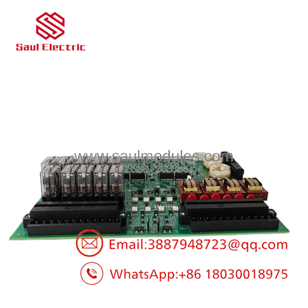
- IS200ESYSH1AAA
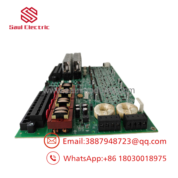
- IS200ESYSH1AAA
Frequently Asked Questions (FAQ)
Can I hot-swap this ESYS card while the turbine is online?
If the system is running a true Triple Modular Redundant (TMR) configuration with active three-way voting (R, S, and T divisions), you can technically replace a single board without forcing a primary master trip. However, this action requires strict adherence to GE live-maintenance procedures. If your system is running a single or simplex channel architecture, pulling this board will cause an immediate loss of control data, resulting in a turbine trip.
What is the specific role of the “H1AAA” designation?
The “H1AAA” code signifies the functional hardware configuration family. The “H1” indicates it belongs to the Group 1 product assembly, while “AAA” tracks the initial factory revision, artwork configuration, and baseline firmware load. When performing replacements, keeping the group designation uniform prevents internal serial bus communication errors.
Why is it critical to wear an ESD strap when handling the IS200ESYSH1AAA?
Like standard high-speed VME and digital logic modules, the ESYS board contains highly sensitive CMOS ICs and high-speed transceivers. These components are prone to latent damage from minor electrostatic discharges that are imperceptible to humans. A static discharge can compromise a component, causing unpredictable field failures weeks after installation.
Do I need to manually flash the firmware on this board during installation?
The primary operational logic and system parameters reside within the central control processors of the Mark VIe/EX2100e ecosystem. Upon a clean boot, the system checks the board’s profile and pushes necessary internal link configurations. However, you must verify that the underlying software firmware baseline in ToolboxST accommodates the H1AAA hardware profile before startup.
How do you confirm the functionality of surplus legacy cards like this one?
Every board undergoes rigorous quality management verification. We carry out an initial physical anti-counterfeit evaluation, followed by an automated circuit trace check. The hardware is then installed in a live GE control testing rack to perform functional verification testing across all serial channels under operational loads before shipping.


 Start Chat


