





Description
Key Technical Specifications
| Parameter | Value |
| Manufacturer | General Electric (GE) |
| Part Number | IS200TBCIH1C |
| Board Functional Acronym | TBCI |
| Number of Inputs | 24 Dry Contact Inputs |
| Excitation Voltage | 24 V DC or 125 V DC (configured via jumper/cabinet settings) |
| System Compatibility | Mark VI Speedtronic Control System |
| Cabling Interface | Two 48-pin ribbon cable connectors (Jz/Jy or Jx channels) |
| Surge Protection | Onboard metal oxide varistors (MOVs) and high-frequency noise filters |
| Terminal Block Style | Two rows of 24-point barrier terminal blocks |
| Operating Temperature | 0 to +60°C |
Product Introduction
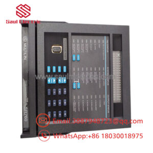
The GE IS200TBCIH1C is a Contact Input Terminal Board (TBCI) manufactured for the Mark VI Speedtronic turbine control system. It acts as the physical interface point for up to 24 discrete dry contact inputs, accepting field signals from pressure switches, limit switches, and auxiliary relay contacts before transmitting them to the control core.
Equipped with robust onboard surge suppression and high-frequency noise filters, the IS200TBCIH1C eliminates field-induced electromagnetic interference (EMI) before it reaches sensitive digital logic. It supports both Simplex and Triple Modular Redundant (TMR) configurations, routing the isolated signals to the VCMI and processor boards via high-density ribbon cables.
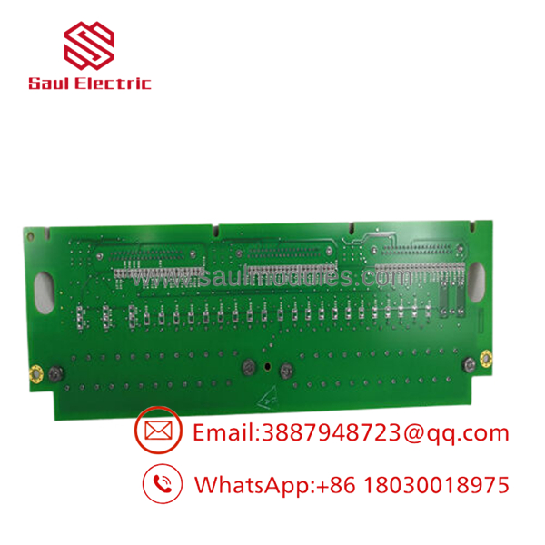
- IS200TBCIH1C
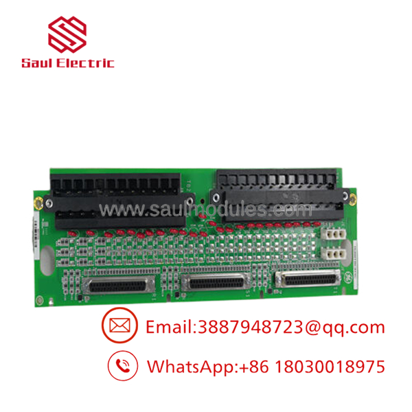
- IS200TBCIH1C
Installation & Configuration Guide
Stage 1: Pre-Installation Preparation
- ⚠️ Safety First: Mark VI cabinets house both low-voltage logic and lethal 125 V DC excitation voltages. De-energize all field circuits routing to this terminal board. Verify the absence of voltage across the terminal strips using a calibrated digital multimeter before proceeding.
- Tools Required: Grounded ESD wrist strap, 3.5mm slotted screwdriver, wire labels, and a digital camera for wire tracking.
- Data Backup: Document the exact positioning of all external field wiring. Note the placement of the internal system ribbon cables attached to the J-connectors.
Stage 2: Removing the Old Module
- Connect your grounded ESD wrist strap to a verified cabinet grounding stud.
- Label each individual field wire matching its corresponding screw terminal number. Disconnect the wires carefully from the barrier strips.
- Unplug the high-density ribbon cables from the onboard Jx, Jy, or Jz connectors by squeezing the side deployment latches.
- Remove the mounting screws holding the PCB to the cabinet chassis backing plate, then lift the board clear.
- ⚠️ Note: Do not drop or misplace the nylon insulation standoffs located behind the board assembly.
Stage 3: Installing the New Module
- Unpack the new IS200TBCIH1C board inside the ESD-safe zone.
- Configuration Clone (Crucial): Examine the hardware revision level and any onboard hardware configuration variables against the original card. Ensure the physical layout matches your cabinet specification exactly.
- Position the card onto the insulation standoffs and tighten the chassis mounting screws securely to establish a proper frame ground interface.
- Snap the system ribbon cables back into their designated Jx/Jy/Jz plug matrix.
- Land the labeled field wires back onto the barrier terminal strips, torquing the screws to 7 in-lbs (0.8 Nm) to avoid stripping the headers.
- Self-Checklist:
- [ ] Ribbon cables are completely seated and the side locks are snapped shut.
- [ ] Field terminal screws are tight and wire labels match perfectly.
- [ ] Standoffs are intact, preventing the PCB from touching the metal enclosure backplate.
Stage 4: Power-On & Testing
- Re-apply the internal cabinet excitation power loop.
- Check the input status indicators inside the control software (Toolbox) to confirm the new card is online and registering with the central rack interface.
- Perform a physical loop verification by systematically closure-testing a select few field contacts, checking that the corresponding software point changes state from 0 to 1 cleanly.
- ⚠️ Troubleshooting Note: If the software reports an open circuit across an entire bank of inputs, verify the integrity of the ribbon cables and check the master cabinet excitation fuse supplying the 24/125 V DC rail to the TBCI board.
Frequently Asked Questions (FAQ)
Can I hot-swap this terminal board while the turbine is operating?
No. While the processor cards in a TMR Mark VI system can sometimes undergo live maintenance, replacing a physical passive terminal board like the requires a complete power shutdown of the associated loop. Disconnecting field terminals or system ribbon cables under live excitation will cause voltage transients, likely dropping multiple inputs simultaneously and triggering an immediate master turbine trip.
What is the specific difference between the “H1C” suffix and older versions like “H1A”?
The “H1C” designation denotes a specific manufacturing artwork revision and components profile assembly under Group 1. The functional schematic remains backward compatible with standard H1 assemblies, but it includes component updates designed to maximize noise rejection. Always confirm that your system baseline drawing notes recognize the specific C-revision footprint.
Do I need to perform a software download after replacing this board?
No. The is a passive termination and filtering board. It contains no programmable flash memory, EEPROMs, or microprocessor chips. All configuration regarding inversion logic or debounce times is stored inside the central I/O processor boards (such as the VCMI or VCRC). Once the physical hardware links are verified, the system will resume polling immediately.
What happens if I accidentally mix up the Jx, Jy, or Jz ribbon cable connections?
In a Triple Modular Redundant (TMR) control architecture, the Jx, Jy, and Jz connectors route the split discrete input signals to the R, S, and T control cores respectively. Crossing these ribbon cables will scramble the voter validation matrix, leading to diagnostic voting mismatch errors in the alarm logs and compromising the redundant safety profile of the system.
Why do you sell these parts as “New Surplus”?
“New Surplus” denotes genuine OEM hardware that was purchased for plant construction, expansion projects, or warehouse critical spares inventories but was never put into active service. These boards are factory original, undergo our comprehensive multi-point diagnostic inspection, and represent a fast, reliable method to bypass extended OEM manufacturing lead times.


 Start Chat


