





Description
Key Technical Specifications
| Parameter | Value |
|---|---|
| Functional Acronym | TREA (Excitation Contact Terminal Board) |
| Board Configuration | S1A (Simplex execution variant) |
| Application Circuit | Emergency Trip / Contact Input-Output interface for EX2100 / Mark VI |
| Contact Voltage Rating | Supports 24 V DC and 125 V DC interrogation configurations |
| Terminal Blocks | 2 x Heavy-duty barrier terminal blocks (typically 48 points total) |
| Cable Interfaces | 2 x Multi-pin ribbon cable connectors for linking to I/O racks |
| Mounting Format | Base panel mounting via nylon standoffs or sheet metal tracks |
| Operating Temperature | −30 to +65 °C (−22 to 149 °F) |
| Storage Temperature | −40 to +85 °C (−40 to 185 °F) |
| Relative Humidity | 5% to 95% non-condensing |
| Physical Footprint | Approximately 17.8 cm × 12.7 cm (7.0 in × 5.0 in) |
Product Introduction
The GE IS200TREAS1A is an Excitation Contact Terminal Board (TREA) engineered for General Electric’s Speedtronic Mark VI turbine control framework and EX2100 excitation systems. Functioning as a high-reliability physical termination block, this simplex-configured board interfaces external emergency trip contacts, trip interlocks, and discrete field signals directly with the primary control processors.
The TREA board is preferred in critical voltage regulation loops because it contains specialized onboard noise suppression components and optocoupler filters. These components prevent inductive feedback and transient voltage spikes from the generator deck from bleeding backward through the multi-pin ribbon cables into the core 32-bit control layer, eliminating ghost trips and data degradation.
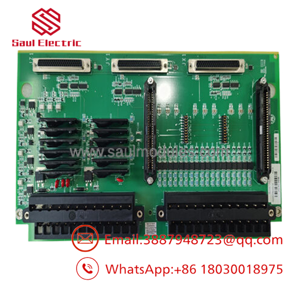
- IS200TREAS1A
Installation & Configuration Guide
Stage 1: Pre-Installation Preparation (Estimated Time: 20 minutes)
- ⚠️ Safety First: Inform operations before touching this card. Isolate all external power sources supplying the terminal blocks on this card, paying close attention to 125 V DC external breaker paths often used for trip strings. Verify a zero-voltage state with your multimeter before disconnecting wires.
- Tools Required: PH2 cross-tip screwdriver, small flathead terminal driver, grounding static-dissipative wrist strap, and a digital multimeter.
- Data Backup: Document or photograph the exact wire-to-terminal mappings on the barrier strips. Mark every wire marker tag clearly to guarantee correct landing on the new module.
Stage 2: Removing the Old Terminal Board (Estimated Time: 10 minutes)
- Secure your ESD wrist strap to a verified frame ground terminal on the enclosure.
- Carefully unplug the multi-pin internal ribbon cables connecting the TREA board to the control rack. Squeeze the side ejector tabs to release the headers smoothly.
- Loosen the terminal screws and extract all field control wires. Tuck them back cleanly to prevent short circuits.
- Unscrew the chassis mounting screws holding the PCB to the cabinet standoffs.
- ⚠️ Note: Lift the board out straight. Do not flex the PCB, as this can crack fine surface-mount resistor layers. Slide the old board directly into an ESD shielding bag.
Stage 3: Installing the New Terminal Board (Estimated Time: 15 minutes)
- Unpack the new IS200TREAS1A on your grounded anti-static mat.
- Configuration Clone: Inspect any physical jumpers or selectable configuration pins on the new board. Ensure they mirror the settings on the card being replaced to match local circuit voltage properties (e.g., 24 V vs. 125 V logic).
- Align the PCB holes with the panel standoffs and tighten the mounting hardware evenly.
- Re-land all field wires onto their exact matching terminal points on the barrier blocks, torqueing the screws to factory specifications.
- Securely click the internal multi-pin ribbon communication cables back into their designated headers.
Stage 4: Power-On & Operational Check (Estimated Time: 15 minutes)
- Re-energize the external interrogation loop breakers and master rack supply lines.
- Measure the voltage across the primary diagnostic check pins on the board to confirm stable 24 V DC or 125 V DC presence.
- Verify that the matching input status registers update correctly within your Toolbox configuration utility.
- Perform a controlled dry-run contact test if the plant schedule permits to ensure the emergency trip circuits transition without signaling gaps.
- ⚠️ Troubleshooting Note: If the control rack reports an “Open Cable” or “Terminal Board Diagnostic Alarm,” shut off power and check the alignment of the multi-pin ribbon cable connectors. A bent pin inside the ribbon header will drop lines and throw immediate hardware tracking faults.
Frequently Asked Questions (FAQ)
What does the “S1A” suffix signify on this Mark VI terminal board?
The S1A suffix designates the exact hardware build revision and topology layout. The “S” signifies a Simplex application profile, meaning it contains a single channel set of terminal tracks designed to route directly to a single I/O control card. This distinguishes it from “T” or “R” triple-modular redundant (TMR) board variants that fork field signals into three independent processing pathways.
Can this board be replaced while the turbine is turning or online?
Absolutely not. The IS200TREAS1A handles critical excitation control strings and emergency trip contact interfaces. Severing wiring links or pulling ribbon cables while the system is online will instantly open loop circuits, drop emergency trip relays, and trigger an immediate, high-stress emergency turbine shutdown.
Why does this board have built-in suppression components across the terminal traces?
Generator excitation and turbine deck environments are subject to severe electromagnetic interference (EMI), radio-frequency noise, and massive voltage transients from inductive relay kicking. The TREA board incorporates high-capacity suppression filters, resistors, and capacitors directly onto its surface layers to clean these incoming signals before they reach the sensitive microprocessors in the control core.
Are the terminal blocks on this card removable, or do I have to unscrew every field wire?
On the standard IS200TREAS1A footprint, the heavy-duty barrier terminal blocks are soldered directly onto the printed circuit board to maintain robust mechanical connection profiles in high-vibration applications. This means you will need to log, unscrew, and re-land each individual field wire when executing a full board replacement.
What is the condition and testing baseline of this discontinued GE board?
These components are New Original / New Surplus items sourced from climate-controlled power station spare pools and canceled upgrade reserves. Because GE has moved past active production pipelines for the legacy Mark VI lines, factory-direct assemblies are no longer produced. We perform thorough physical trace examinations, component checks, and continuity tests to guarantee out-of-box functionality, and back this card with a complete 1-year warranty.



 Start Chat


