





Description
Key Technical Specifications
| Parameter | Value |
| Number of Channels | 2 Independent Hydraulic Servo Channels |
| Valve Drive Current | Configurable: ±10 mA, ±20 mA, ±50 mA, ±100 mA |
| Feedback Sensor Inputs | LVDT (Linear Variable Differential Transformer), RVDT, Pulse Rate |
| Excitation Voltage | 7.0 kHz AC nominal for LVDT/RVDT sensors |
| System Interface | Dual-cable connection to VPRO / VSVO processor modules |
| Terminal Blocks | Two rows of 24-point barrier terminal blocks (48 points total) |
| Operating Temperature | 0 to +60 °C (32 to 140 °F) |
| Relative Humidity | 5% to 95% non-condensing |
Product Introduction
The GE IS200TSVCH1AED is a dedicated Servo Terminal Board manufactured for the Mark VI Speedtronic turbine control system. It provides the physical and electrical interface between the high-speed digital control processors and the hydraulic actuators used on steam or gas turbines. By bridging the gap between control logic and field hardware, the board ensures precise positioning of fuel and steam valves.
Plant operators select the IS200TSVCH1AED revision because it contains specific hardware modifications that improve signal filtering on the LVDT excitation loops compared to older H1A or H1B iterations. The board features dual-channel redundancy, allowing a single terminal board to feed discrete position demands to multiple coil servo actuators, preventing a single point of failure from causing a turbine trip.
Installation & Configuration Guide
Stage 1: Pre-Installation Preparation (Estimated Time: 15 minutes)
- ⚠️ Safety First: Valve control circuits interface directly with high-pressure hydraulic lines. Ensure the turbine is in a safe, cold shutdown state. Lock out and tag out the hydraulic skid power supplies. Wait 5 minutes for internal capacitor banks on the associated power distribution modules to discharge fully.
- Tools Required: ESD wrist strap, Fluke 115 multimeter, 3.5 mm slotted screwdriver, wire markers, digital camera or smartphone.
- Data Backup: Access the Toolbox software. Document the exact calibration values, null-bias offsets, and gain settings for the servo loops tied to this specific slot. Photograph the terminal block layout and cable routing.
Stage 2: Removing the Old Module (Estimated Time: 10 minutes)
- Unclip the plastic protective faceplate from the terminal board housing.
- Label each wire landing on the terminal blocks using the terminal numbers (1 through 48) as a guide.
- Loosen the terminal screws and carefully remove the field wiring. Do not pull on the insulation. Secure the loose bundles away from the backplane.
- Disconnect the J-type ribbon or core communication cables connecting the TSVC board to the VSVO/VPRO VME rack modules.
- Back out the mounting screws holding the PCB to the cabinet sheet metal. Pull the card straight toward you to avoid scraping neighboring components.
- ⚠️ Note: Retain the failed board. You may need to verify its onboard hardware jumper configurations if the system configuration files in the software do not match the physical asset.
Stage 3: Installing the New Module (Estimated Time: 15 minutes)
- Ground yourself using an ESD wrist strap attached to a verified chassis ground. Remove the new IS200TSVCH1AED from its anti-static bag.
- Configuration Clone (Crucial): Lay the old board and the new board side by side. Locate all hardware jumpers (e.g., excitation frequency filters or current range selectors). Replicate the exact jumper positions from the old board onto the new board.
- Align the new board with the mounting standoffs in the cabinet. Tighten the mounting screws evenly; do not over-torque, as this can crack the multi-layer PCB.
- Land the field wires onto the terminal blocks using a 3.5 mm slotted screwdriver. Ensure clean contact and verify that no stray wire strands bridge adjacent terminals.
- Reconnect the system interface cables to the VME rack modules, making sure the connector locking tabs click into place.
- Self-Checklist:
- [ ] Jumpers match the old board exactly.
- [ ] Terminal wiring torqued to specification, zero loose strands.
- [ ] System interface cables firmly seated and locked.
Stage 4: Power-On & Testing (Estimated Time: 20 minutes)
- Pre-Power Check: Use a multimeter to verify there is no dead short between the 24 V / 125 V DC power inputs and the chassis ground on the terminal strips.
- Apply logic power to the Mark VI control rack. Do not turn on the hydraulic pumps yet.
- Check the diagnostic LEDs on the associated VSVO processor card. The RUN LED should show solid green. If a red DIAG or FLT light activates, check the software log.
- Establish communication via Toolbox software. Check that the board revision “H1AED” is recognized by the system firmware.
- Run a standard servo calibration routine through the software to verify LVDT feedback alignment and null-bias points before introducing hydraulic pressure.
- ⚠️ Troubleshooting Note: If the software reports an “LVDT Open Circuit” fault immediately after power-up, check terminals for loose connections or verify that your AC excitation voltage jumper matches the sensor requirements.
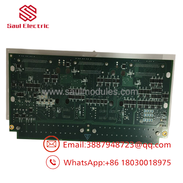
- IS200TSVCH1AED
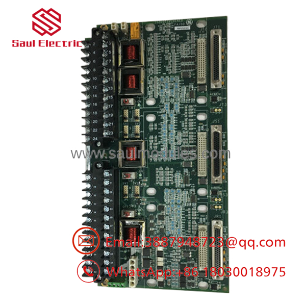
- IS200TSVCH1AED
Frequently Asked Questions (FAQ)
Can this board be hot-swapped while the turbine is running?
No. Absolutely do not attempt to hot-swap the IS200TSVCH1AED. This board directly drives the servo coils for critical fuel and steam valves. Severing the connection under power drops the valve drive current to 0 mA, forcing the valve to its fail-safe position. This will cause an immediate turbine trip. Additionally, breaking live inductive connections can damage the driver transistors on the upstream VSVO module. Turn off the system power before replacement.
What do the trailing letters “AED” signify in the model number?
The letters indicate the revision history of the board.
- “H1” denotes the standard hardware group (typically a dual-channel servo layout).
- “A”, “E”, and “D” represent subsequent factory design updates, component changes, or firmware compatibility patches.
A board with an “AED” suffix includes improved noise filtering and replaces older “AAB” or “ABA” iterations. It is generally backward-compatible, but you must verify that your Mark VI system firmware version supports the “AED” revision level in the configuration tree.
What happens if my jumpers do not match the old board?
If the jumpers are misconfigured, the servo loop will not function correctly, or you might damage your field instruments. For example, if the jumpers are set for a ±10 mA output but your servo coil requires ±100 mA to reach full stroke, the valve will not open sufficiently, leading to position tracking faults. Always take a high-resolution photo of the old board’s jumpers before removing it.
Will I lose my calibration data when I replace this board?
The calibration parameters (offsets, gains, and filter constants) are stored in the flash memory of the VSVO controller card or within the master Toolbox project files, not on the terminal board itself. However, because new components have minor manufacturing tolerances, you must perform a standard stroke calibration after installation to ensure precise position feedback.
Why is your price lower than the OEM factory list price?
We source our parts from industrial surpluses, cancelled automation projects, and system upgrades. Because we buy this inventory through direct channels rather than the traditional OEM distribution network, we can pass the savings directly to you. Every board undergoes a strict inspection and testing protocol to ensure it functions exactly like a direct-from-factory component.


 Start Chat


