





Description
Key Technical Specifications
| Parameter | Value / Specification |
| System Architecture | GE Mark VI / Mark VIe Speedtronic Turbine Control |
| Functional Acronym | TSVC (Servo Input/Output Terminal Board) |
| Manufacturing Code | MRP061873 |
| Revision Level | H2A with DC modification tier |
| Servo Output Channels | 2 independent bi-directional servo valve current drivers |
| Configurable Output Currents | 10 mA, 20 mA, 40 mA, 80 mA, 120 mA nominal loops |
| Position Feedback Support | Linear Variable Differential Transformers (LVDT) / RVDT |
| Excitation Supply | Onboard high-frequency AC excitation for position sensors |
| Suicide Relays | Integrated hardware safety suicide relays per servo loop |
| PCB Protection | High-grade industrial conformal coating |
| System Redundancy | Connects to Simplex, Dual, or TMR (Triple Modular Redundant) I/O packs |
Product Introduction
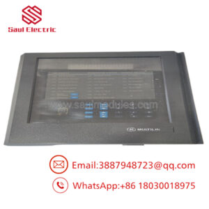
The GE IS200TSVCH2ADC, bearing factory assembly identifier MRP061873, is a specialized Servo Input/Output Terminal Board designed for GE Mark VI and Mark VIe Speedtronic turbine control systems. This block serves as the critical real-time interface connecting digital control logic to the physical electro-hydraulic actuators regulating fuel stroke, steam governor valves, and guide vanes. It processes precise closed-loop positioning calculations by driving targeted current commands down to the fluid actuators while simultaneously monitoring return tracks.
Equipped to operate in Simplex, Dual, or Triple Modular Redundant (TMR) architectures, the board provides structural conditioning for Linear Variable Differential Transformers (LVDTs) and Rotary Variable Differential Transformers (RVDTs). It utilizes high-frequency AC excitation circuits to capture real-time position measurements down to micro-inch tolerances. For protection, the module includes dedicated onboard hardware suicide relays that instantly isolate output currents if an upstream logic mismatch or processor watchdog failure is flagged, preventing erratic valve positioning.
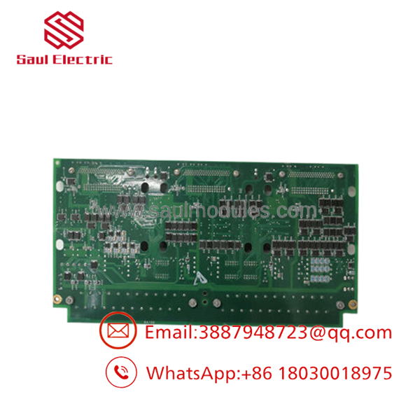
- IS200TSVCH2ADC MRP061873
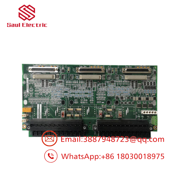
- IS200TSVCH2ADC MRP061873
Installation & Configuration Guide
Stage 1: Pre-Installation Preparation (Estimated Time: 15 minutes)
- ⚠️ Safety First: Replacing a servo interface board can cause unexpected, abrupt valve travel if fluid systems are live. Never execute a replacement while the turbine is online or hydraulic systems are pressurized. Isolate the high-pressure oil/fuel supplies. Lock out and tag out (LOTO) all 28 VDC control power rails feeding the terminal base.
- Tools Required: Grounded static wrist strap, magnetic PH2 screwdriver, fine-tipped terminal tool, digital multimeter (DMM).
- Data Backup: Utilize ToolboxST or Toolbox software to compile a complete point configuration file. Document calibration scaling values, nominal null currents, and current bias variables assigned to the specific servo channels.
Stage 2: Removing the Old Module (Estimated Time: 10 minutes)
- Snap your ESD wrist strap to an unpainted, structural grounding point on the control cabinet frame.
- Carefully unplug the low-voltage communication ribbon cables or high-density I/O packs (such as PSVO or WSVO units) docked directly onto the terminal board connectors.
- Tag all field wire pairs landed across the barrier strips with their respective LVDT or coil designations (e.g., Coil 1+, LVDT A Exc+).
- Back out the terminal screws and remove the field conductors. Wrap or route them clear of the chassis to avoid grounding.
- Unscrew the retention fasteners clamping the TSVC plate assembly onto the interior cabinet backing tracks, then pull the board straight outward.
Stage 3: Installing the New Module (Estimated Time: 15 minutes)
- Unpack the new IS200TSVCH2ADC (MRP061873) board inside your designated static-safe envelope.
- Configuration Clone: Lay the retired board and the replacement card side by side. Carefully examine and duplicate any physical jumper links or sliding configuration switches that scale output milliamp thresholds or configure shield grounding choices.
- Position the replacement plate square against the mounting footprints and secure the hardware framework down tightly.
- Reland the LVDT and servo valve field conductors to their designated screw terminal points, checking for tight connections to avoid trace impedance.
- Securely dock the active control processors or interconnecting logic harnesses back into place.
Stage 4: Power-On & Testing (Estimated Time: 25 minutes)
- Use a multimeter to run a quick continuity loop check, confirming the board’s frame layout bonds cleanly to the main system ground bus.
- Return control energy to the rack bus bar. Do not apply hydraulic pressure yet.
- Check that the diagnostic lights on the board stay green and that no major hardware faults appear in the engineering workstation logs.
- Servo Valve & LVDT Calibration: Before pressurizing hydraulic headers, run a standard software-guided valve calibration script via ToolboxST. Verify that the feedback signals respond linearly as the manual output stroke commands change from 0% up to 100%.
Frequently Asked Questions (FAQ)
Can I change out this board while the turbine is running if I have a TMR setup?
No. Even though a Triple Modular Redundant (TMR) control framework utilizes three isolated processing cores, the physical IS200TSVCH2ADC is a simplex terminal module where the physical lines for the servo coils and LVDT sensors converge. Pulling this board immediately severs the physical wiring links to the fuel and steam regulating loops, resulting in an instant, unpreventable trip condition.
What does the “MRP061873” code represent on my component tag?
The designation is the exact internal manufacturing bill-of-materials and assembly reference code used by GE during factory production. While the primary alphanumeric designation (IS200TSVCH2ADC) points to the generic functional board layout and its revision levels, matching the factory MRP tracking index confirms that the components, tracking tolerances, and internal component choices line up identically with your original turbine delivery package.
Why do the servo output loops include a “suicide function”?
The current loop “suicide function” is a built-in hardware failsafe system. If an onboard watchdog check registers a severe failure—such as a configuration error, a stuck control relay, or an internal digital-to-analog converter conflict—the board automatically energizes an inline suicide relay. This drops the servo drive loop current down to zero, allowing the valve’s mechanical springs to safely push the fuel or steam path closed.
Can this board be used with standard 4-20mA positioning actuators?
No, the is specifically tailored to drive true bi-directional servo coils (typically using distinct rating nodes like 10mA, 20mA, 40mA, 80mA, or 120mA) and process raw high-frequency AC signals from LVDTs. It cannot natively interface with common 4-20mA loops or 0-10V automated control valves without using separate external signal converters.
How should I troubleshoot a “Position Feedback Discrepancy” fault after an installation?
An immediate tracking discrepancy fault usually points to an off-center physical configuration jumper or an LVDT calibration shift. Power down the subsystem, double-check that your hardware jumper blocks are mirrored precisely from the old board, verify that the wire leads for the primary and secondary LVDT channels are not swapped, and rerun the full loop position sensor calibration wizard inside your software application.


 Start Chat


