





Description
Key Technical Specifications
| Parameter | Value |
| Manufacturer | General Electric (GE) |
| Part Number | IS200VSVOH1B |
| Functional Acronym | VSVO |
| Revision Level | H1B (Group 1, Second-Generation Functional Design) |
| Servo Output Channels | 2 Independent Channels (supports ±10 mA, ±20 mA, ±40 mA, or ±100 mA configurations) |
| Position Feedback Inputs | Linear Variable Differential Transformers (LVDT) / Rotary Variable Differential Transformers (RVDT) |
| Excitation Outputs | 7 V RMS, 3.2 kHz high-accuracy AC excitation voltage for position sensors |
| System Voting Mode | Simplex or Triple Modular Redundant (TMR) 2oo3 configuration |
| System Compatibility | Mark VI Speedtronic VME Rack Systems |
| Terminal Board Match | Interfaces explicitly with TSVOH1A or TSVOH1B terminal assemblies |
| Front Panel Diagnostics | 3 Status LEDs (RUN – Flashing Green, FAIL – Solid Red, STATUS – Yellow) |
Product Introduction
The GE IS200VSVOH1B is a high-speed VME Servo Control Board (VSVO) engineered for the Mark VI Speedtronic turbine control matrix. This card handles closed-loop position regulation for electro-hydraulic servo valves controlling critical gas and steam turbine components, including primary fuel valves and inlet guide vanes (IGVs).
Equipped with dual independent servo channels and dedicated high-accuracy AC excitation drivers for LVDT/RVDT feedback loops, the IS200VSVOH1B executes control algorithms at ultra-fast update rates. It functions as a Group 1 “H1B” asset, integrating smoothly into Triple Modular Redundant (TMR) networks to maintain stable, vibration-resistant fuel metering under severe transient load shifts.
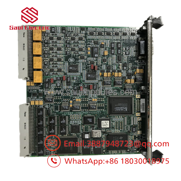
- IS200VSVOH1B
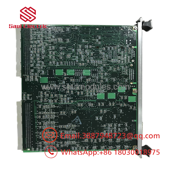
- IS200VSVOH1B
Installation & Configuration Guide
Stage 1: Pre-Installation Preparation
- ⚠️ Safety First: The VSVO card drives fuel and steam control valve actuators. Mistakes during replacement can cause an un-trippable overspeed event or severe mechanical surge. Ensure the turbine is completely shutdown and the fuel isolation manual valves are locked out and tagged out (LOTO). Power off the targeted VME card rack division before hardware handling to prevent backplane bus shorts.
- Tools Required: Grounded anti-static (ESD) wrist strap, ESD protection mat, small flathead screwdriver, and a digital multimeter.
- Data Backup: Open the Toolbox software environment. Upload and backup your active servo calibration constants, stroke limits, null shifts, and LVDT/RVDT excitation scaling parameters.
Stage 2: Removing the Old Module
- Securely clip your grounded ESD wrist strap to a bare metal frame point on the VME cabinet chassis.
- Back out the upper and lower captive locking screws embedded in the single-width card faceplate.
- Simultaneously pull the top and bottom ejector ears outward to unseat the card from the high-density VME backplane pins.
- Smoothly pull the card along the slot guides out of the rack assembly.
- ⚠️ Note: Immediately slide the removed VSVO card into an ESD shielding pouch to protect sensitive CMOS components and analog signal processors.
Stage 3: Installing the New Module
- Keep the replacement IS200VSVOH1B inside its sealed anti-static packaging until the exact moment of physical insertion.
- Configuration Clone (Crucial): Cross-check the board label identifiers. Note that the “H1B” revision specifically requires matching compatibility with either the TSVOH1A or TSVOH1B terminal board variants. Ensure any physical hardware jumpers on the terminal cards match the target servo coil current ratings (e.g., 10 mA vs. 40 mA).
- Align the edges of the card PCBA with the plastic rack slot tracks and slide the card smoothly inward.
- Firmly engage the faceplate levers inward to mate the card edge connectors with the rear backplane pins, then tighten the top and bottom captive screws.
- Self-Checklist:
- [ ] Board is seated flush and locked tightly via front-panel levers.
- [ ] Captive frame screws are secured to ensure proper reference grounding.
- [ ] Associated TSVO terminal board jumpers match the exact field servo current specs.
Stage 4: Power-On & Testing
- Restore control voltage to the VME processor rack assembly.
- Observe the front-panel indicator LEDs during the startup sequence: the RUN LED must transition to flashing green, and the FAIL indicator must remain dark.
- Access the Toolbox configuration environment to confirm the online status of the new board without compilation errors.
- Execute Valve Calibration: Before attempting a turbine ignition sequence, run a complete servo valve auto-calibration routine via Toolbox to verify LVDT/RVDT feedback tracking and to confirm the hardware null shift aligns correctly across 0% to 100% stroke range.
- ⚠️ Troubleshooting Note: If a
L3DIAG_VSVOposition feedback error or LVDT open-circuit fault triggers, check the AC excitation voltage levels at the TSVO terminal block and verify the external sensor cable shield grounding.
Frequently Asked Questions (FAQ)
Can I hot-swap this VSVO card while the turbine is online?
No. Even if your Mark VI control system is configured as a Triple Modular Redundant (TMR) system, the VSVO card drives a central hydraulic valve actuator. Removing a card division under power can disrupt the current balance across the multi-coil servo valve, leading to erratic fuel valve movement or an immediate emergency turbine trip. Power down the designated rack division before swapping.
What is the mechanical role of the “H1B” suffix on this card?
The “H1B” designation tracks the hardware revision level, structural artwork modifications, and underlying component lifecycle updates implemented by General Electric. Boards featuring the “H1B” suffix preserve the foundational backward compatibility framework for Group 1 architectures, but they incorporate upgraded output transistor sets optimized to handle transient inductive back-EMF spikes from heavy actuator coils.
Why does this board use AC voltage for position feedback instead of standard 4-20 mA?
The utilizes a 3.2 kHz AC excitation voltage to interface with Linear Variable Differential Transformers (LVDTs). LVDTs are non-contact inductive sensors preferred in high-vibration turbine environments because they lack internal slide contacts that wear out. The VSVO board converts the returning AC voltage phase and amplitude directly into a highly precise, noise-immune linear position measurement.
What happens if the servo output current trips a diagnostic fault code?
The servo loop circuitry on the incorporates continuous loop monitoring. If the card detects an open circuit, a shorted servo coil, or an unexpected current deviation between voted channels, it immediately triggers a diagnostic alarm. In severe loop faults, the hardware failsafe open-collector circuits will clamp the affected servo channel loop to protect the mechanical actuator from driving hard against its physical stops.
Do I need to perform a software compilation down-load after mounting this board?
No software modifications or firmware uploads are required. The acts as a hardware interface and driver card. It does not carry microprocessors or internal flash memories that retain user program code. All processing instructions and logic configurations occur in the main control processors. However, physical servo calibration via the software interface is mandatory to align the new card with the physical valve limits.



 Start Chat


