





Description
Key Technical Specifications
| Parameter | Value |
|---|---|
| Compatibility | Interfaces with 1 x Hydran 201Ti Intelligent Transmitter |
| Measurement Range | 0 to 2,000 ppm (Volume/Volume, H2 equivalent) |
| Input Supply Voltage | 115 V AC or 230 V AC nominal, selectable; 50/60 Hz |
| Power Capacity | 120 VA maximum (includes internal thermostatically controlled heater) |
| Primary Analog Output | Isolated 4–20 mA loop, 0–2000 ppm mapping |
| Secondary Analog Output | 0–1 mA non-isolated local test point |
| Local Interface Display | Backlit LCD, 2 lines by 16 alphanumeric characters |
| Alarm Relays | 3 x SPDT (Type C) contacts: Gas Hi, Gas Hi-Hi, and System Fail |
| Contact Load Rating | 60 W / 125 VA; 220 V DC / 250 V AC maximum |
| Serial Communication | 1 x RS-485 network link, 1 x RS-232 local diagnostic port |
| Enclosure Rating | NEMA 4X / IP66 weatherproof treated aluminum housing |
| Operating Temperature | −50 to +55 °C (−58 to 131 °F) with internal heater active |
Product Introduction
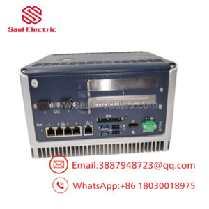
The GE Hydran H201Ci-1 (often cataloged as H20CI-1) is a specialized one-channel electronic controller designed to process real-time analytics from a Hydran 201Ti intelligent dissolved gas transmitter. Installed on power transformers, reactors, and oil-filled electrical assets, this system provides early warning diagnostics by continuously calculating volatile combustible gas tracking—primarily Hydrogen (H2) and Carbon Monoxide (CO).
PLCMO
By translating weak data links from the valve-mounted transmitter into isolated 4–20 mA outputs and Modbus-compatible RS-485 streams, the H201Ci-1 allows maintenance teams to detect thermal tracking, arcing, and cellulosic insulation breakdown before catastrophic field failures occur. Housed in a weatherproof, heated NEMA 4X enclosure, it serves as a reliable field monitor capable of operating on substation decks subject to extreme sub-zero or high-ambient temperatures.
PLCMO
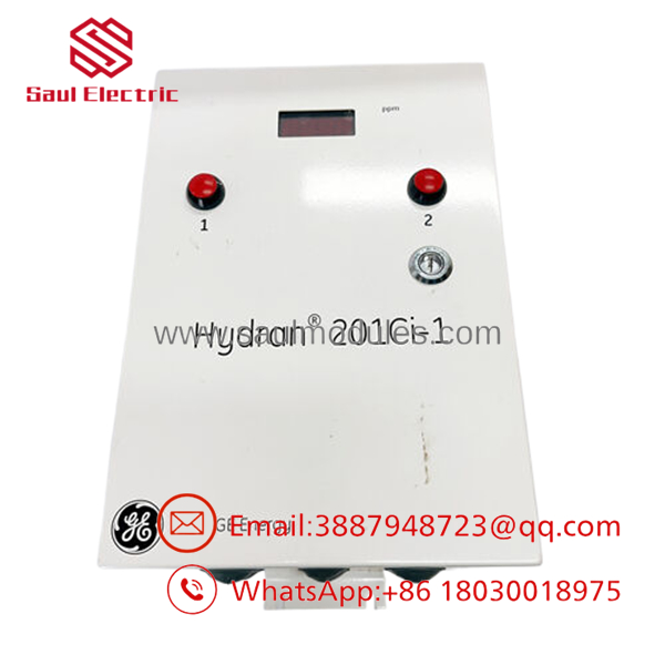
- H201Ci-1
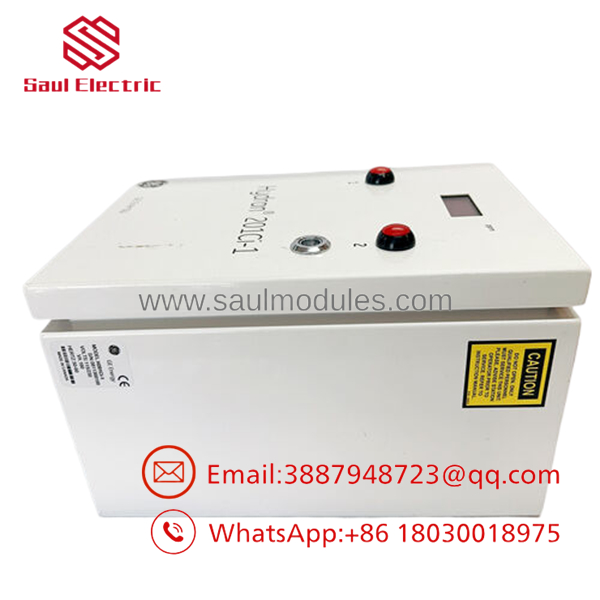
- H201Ci-1
Installation & Configuration Guide
Stage 1: Pre-Installation Preparation (Estimated Time: 15 minutes)
- ⚠️ Safety First: De-energize or bypass the specific alarm and trip relay circuits on the substation panel tied to this monitor to avoid false alarms during installation. Ensure the main AC breaker box feeding the layout is tagged out.
- Tools Required: Grounded ESD wrist strap, small flathead terminal driver, precision wire strippers, and a digital multimeter.
- Data Backup: If replacing an operational unit, document the exact parameter settings from the old LCD menu, specifically the high/high-high alarm thresholds, target baud rates, and any local analog scaling offsets.
Stage 2: Removing the Old Controller (Estimated Time: 10 minutes)
- Turn off the primary AC power breaker and open the NEMA 4X cabinet door.
- Verify with your multimeter that no voltage remains on the line-in terminals.
- Unplug or unscrew the field terminal blocks housing the 4–20 mA loop, the transmitter link connections, and the alarm relays.
- Unbolt the enclosure from its mounting rack or structural wall plate.
- ⚠️ Note: If the assembly uses anti-vibration mounts, check them for structural degradation or dry rot before positioning the replacement enclosure.
Stage 3: Installing the New Controller (Estimated Time: 20 minutes)
- Mount the replacement H201Ci-1 cabinet onto the vibration-absorbing plate at eye level for readability.
- Voltage Selection Verification (Crucial): Before applying line power, verify the internal voltage selector switch or jumper position matches your local grid layout (115 V AC or 230 V AC).
- ⚠️ Warning: Powering a unit configured for 115 V with 230 V line lines will blow the transformer board and internal fuse links instantly.
- Route the supervisory link cable from the 201Ti transmitter through the designated bottom conduit entry hub and terminate the shield ground according to the wiring diagram.
- Connect your relay blocks, analog loops, and mains power wires to the matching card headers.
Stage 4: Power-On & Testing (Estimated Time: 15 minutes)
- Energize the incoming AC line breaker.
- The backlit LCD display should initialize, activate the internal enclosure heater, and read out local gas ppm thresholds.
- Use the 6-key front keypad to program your documented alarm setpoints and configuration parameters.
- Verify that the FAIL relay contact is satisfied (closed during normal operation) and that the red diagnostic indicators match safe parameters.
- ⚠️ Troubleshooting Note: If the display blanks out or shows a permanent “Transmitter Comms Fail” alert, inspect the DC supply voltage driving out to the valve-mounted 201Ti transmitter and check for loose or reversed wiring paths on your communication link terminals.
Frequently Asked Questions (FAQ)
Can the H201Ci-1 controller be installed outdoors without an extra sunshield?
Yes, the controller comes housed inside a rugged, sealed NEMA 4X (IP66) enclosure that withstands rain, blowing snow, and corrosive industrial environments. However, in regions with extreme summer temperatures, installing a simple protective sunshield is highly recommended to prevent direct UV solar load from overheating the internal electronics and making the LCD difficult to read.
My original part number says H20CI-1, but your documentation says H201Ci-1. Are they identical?
Yes. The formal factory model designation is H201Ci-1, but field engineers, maintenance databases, and procurement platforms often write it as H20CI-1 or H201C1. As long as the suffix indicates -1 (denoting a one-channel remote electronic controller for a single sensor link), the hardware boards and functionality are identical.
Do I need to calibrate the H201Ci-1 controller box itself?
No, the primary calibration variables, gas calculation curves, and sensor coefficients live inside the microprocessor of the valve-mounted Hydran 201Ti Intelligent Transmitter. The H201Ci-1 controller acts as the remote user interface, power provider, and communications manager. When you swap this box, you only need to re-verify local setpoints, outputs, and network properties.
What causes a “Fail” relay event on this specific unit?
The System Fail relay is a normally energized, fail-safe contact loop. It will open—indicating an un-executable status—if the controller loses primary AC power, if the internal thermostatically controlled cabinet heater stops functioning in freezing conditions, or if the digital supervisory link to the remote oil sensor card drops communication packets for an extended period.
Since this Hydran 201i system is an older legacy model, what is the status of this stock?
These units are New Original / New Surplus items sourced from power utility warehouse reserves and canceled substation build packages. Because GE has evolved the Hydran line into newer multi-gas tracking platforms (like the Hydran M2 or Intelligent Transformer Monitor series), these standalone one-channel controllers are hard to acquire. We run complete bench tests on power paths, logic loops, and relay responses to ensure they function perfectly out of the box.


 Start Chat


