





Description
Key Technical Specifications
| Parameter | Value |
| Functional Acronym | WEOR (Wind Energy Operation / Wind Turbine Output Board) |
| System Compatibility | GE 1.5 Megawatt (1.5MW) and related wind turbine platforms |
| Control Series Platform | PACSystems Mark VIe Speedtronic Architecture |
| Board Group Variant | Group 1 Execution |
| Primary Capacitors | 2 x Nichicon 270 \muF electrolytic components rated for 150 °C (C1, C3) |
| High-Voltage Filter Cap | 1 x 3 kV single-layer ceramic capacitor (C2) |
| Onboard Power Resistors | 15 x integrated resistors (including 6 x heavy-duty 100 Ohm variants) |
| Circuit Board Coating | Standard factory-applied protective insulation profile |
| Hardware Revision Rating | Revision A (Functional Suffix G1A) |
| Country of Origin | Salem, Virginia, USA |
Product Introduction
The GE IS200WEORG1A is a specialized Wind Turbine Output / Wind Energy Operation Board (WEOR) developed by GE Energy for the Mark VIe Speedtronic turbine control matrix. Deployed heavily across global wind power generation infrastructure—most notably within standard GE 1.5MW turbine variants—this safety and execution board works alongside control modules to direct power distribution, circuit pitching adjustments, and critical braking array outputs.
The WEOR board stands out for its high-thermal-endurance design, layout optimized for the harsh environments of nacelle housings. Its circuit footprint features specialized heavy-duty component arrays, including dual Nichicon 270 \muF electrolytic capacitors rated for extreme temperatures up to 150 °C and a 3 kV high-voltage ceramic filter capacitor. This configuration provides superior voltage filtering and noise damping, safeguarding core processor logic blocks against volatile grid dynamics and transient lightning strikes common to wind farm towers.
Installation & Commissioning Guide
Stage 1: Pre-Installation Preparation (Estimated Time: 15 minutes)
- ⚠️ Safety First: Lock out and tag out the main breaker paths feeding the turbine’s control cabinet or pitch/yaw distribution bus inside the nacelle. Working inside the control box while live power lines exist poses an arc-flash risk and can easily compromise delicate micro-circuit components via tracking shorts.
- Tools Required: Grounded static-dissipative ESD wrist strap, small flathead screwdriver, long nose pliers, and a digital multimeter.
- Data Logging: Ensure you record the firmware revision and active I/O map configurations from your toolbox management application software before physical extraction.
Stage 2: Removing the Defective Card (Estimated Time: 5 minutes)
- Securely connect your ESD ground wrist strap to a bare metal terminal block on the panel frame.
- Carefully unplug any internal power distribution links and logic communication ribbons leading to the module.
- Undo the perimeter circuit board securing screws anchoring the PCB assembly to its mounting panel standoffs.
- ⚠️ Note: Pull the card cleanly outward from its standoffs, keeping it perpendicular to the back plate. Avoid bending the card chassis or scraping surface trace paths against nearby guide structures. Immediately seal the pulled assembly inside a static-shielding bag.
Stage 3: Installing the New WEOR Board (Estimated Time: 10 minutes)
- Slide the replacement IS200WEORG1A board out from its protective factory wrap while positioned on an ESD-safe workbench mat.
- Check that all physical layout designations, resistor groups, and jumper pins mirror the board parameters of the old card.
- Align the mounting holes with the chassis nylon spacing standoffs and gently press down on the module center until it sits flat.
- Replace and snug down the perimeter panel screws evenly to create an even structural ground connection. Do not over-torque, as this can crack the multi-layer resin board.
- Securely push the multi-pin logic ribbon lines and auxiliary cable power feeds back into their keyed slot seats.
Stage 4: Power-On Validation (Estimated Time: 15 minutes)
- Clear the electrical enclosure of any loose components or tracking tools, then re-energize the primary turbine control circuit breaker.
- Measure voltage levels at the on-board check pads to ensure the card’s internal filters are correctly processing distribution bus inputs.
- Access the turbine diagnostic utility panel via your engineering terminal. Ensure that the new output board registers online without signaling timeouts or internal revision tracking conflicts.
- ⚠️ Troubleshooting Note: If the system triggers an immediate “Output Board Communication Fault,” shut down power and inspect the internal logic ribbons. Even a small piece of dust trapped in a high-density socket pin can interrupt diagnostic polling sequences.
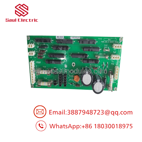
- IS200WEORG1A
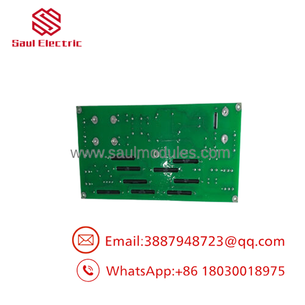
- IS200WEORG1A
Frequently Asked Questions (FAQ)
Which specific turbine models utilize the IS200WEORG1A board?
The WEOR board is prominently used within the control systems of GE 1.5 Megawatt (1.5MW) wind turbine series platforms. It interfaces directly with Mark VIe control panels to manage and process high-power discrete signals and safety outputs.
What is the function of the large 150 °C rated Nichicon capacitors on this board?
The nacelle enclosures of wind turbines encounter severe environmental variations, ranging from sub-zero winter temperatures to high-ambient summer environments, compounded by internal cabinet heat. The dual Nichicon 270 \muF electrolytic capacitors (C1 and C3) are rated up to 150 °C to prevent premature degradation, fluid leakage, or capacitance drift, ensuring stable voltage regulation and long-term filtering reliability.
Does the IS200WEORG1A require separate firmware flashing upon installation?
No, the board functions as a physical interface and output distribution card rather than a standalone application processor. It maps and routes execution logic commands generated by the primary Mark VIe control core. As long as your hardware grouping configuration properties inside the control tracking software match the hardware version, the board operates plug-and-play.
Why is it difficult to find comprehensive factory manuals for this specific board online?
General Electric handles wind turbine control sub-systems primarily through proprietary internal support channels and direct wind farm developer asset documentation. Consequently, individual piece-part user guides for cards like the are rarely published as standalone PDFs online. Instead, their technical data is embedded within the overarching site-specific Mark VIe field integration manuals.
Since active production has shifted to newer generations, what is the status of this stock?
This item is available as a verified New Original / New Surplus component sourced from climate-controlled utility reserves and infrastructure spare parts pools. Since these legacy components are hard to acquire via standard distribution channels, we run every board through comprehensive physical trace examinations and component continuity tests to ensure out-of-the-box reliability. Each unit is backed by our full 1-year independent warranty.


 Start Chat


