





Description
Key Technical Specifications
| Parameter | Value |
|---|---|
| Manufacturer | GE Energy |
| Model Number | IS210AEDBH4AGD |
| Product Type | AE DB Bridge Interface Board |
| Platform | Mark VI Speedtronic Turbine Control System |
| Primary Function | Analog Electronics (AE) to Digital Bus (DB) interface |
| System Application | Gas and steam turbine control |
| PCB Assembly | IS210 modular board |
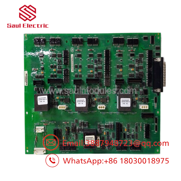
| Transformers | Four encapsulated pulse transformers |
| Hipot Rating (Transformers) | 5 kVAC |
| Switching Frequency | 10 kHz to 500 kHz |
| PCB Construction | Double-sided populated circuit board |
| Connectors | Multiple headers, cable connectors, and pin connectors |
| Installation | Mark VI control cabinet |
Product Introduction
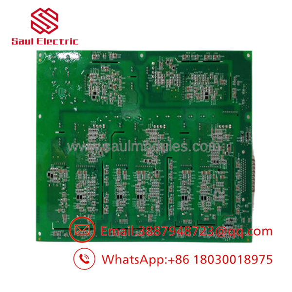
The GE IS210AEDBH4AGD is an AE DB Bridge Interface Board designed for the GE Mark VI Speedtronic turbine control system. It provides the communication bridge between the Analog Electronics (AE) subsystem and the Digital Bus (DB), allowing critical turbine control data to move reliably between hardware sections within the controller.
The board is installed in gas and steam turbine control cabinets where dependable signal isolation and communication are required. It incorporates multiple pulse transformers, isolation circuitry, and a large number of integrated circuits to support continuous turbine operation. Before installation, verify the complete hardware revision and connector configuration against the existing Mark VI system documentation.
- IS210AEDBH4AGD
- IS210AEDBH4AGD
Troubleshooting Quick Reference
| Symptom | Possible Cause | Relevance to this Part | Quick Check Method | Recommendation |
|---|---|---|---|---|
| AE communication loss | Loose bridge board connection | ✅ High | Reseat the board and inspect connector pins | Verify connectors before replacement |
| Multiple subsystem faults | Digital bus communication failure | ✅ High | Review Mark VI diagnostics for bus errors | Confirm backplane health before replacing the board |
| Controller boots but devices unavailable | Bridge interface malfunction | ✅ High | Verify communication across AE and DB interfaces | Replace board after confirming external wiring |
| Intermittent communication | Oxidized connector contacts | ✅ Medium | Inspect and clean edge connectors | Reinstall and retest |
| Random diagnostic alarms | Cabinet power fluctuation | ❌ Low | Measure control cabinet supply voltage | Correct power issue before replacing hardware |
| Board not detected | Incorrect hardware revision | ✅ Medium | Verify full part number and revision suffix | Install the correct hardware revision |
| Burned components visible | Electrical surge | ✅ High | Inspect transformers and PCB for thermal damage | Replace the board and investigate the surge source |
Technical Note: Communication failures in Mark VI systems are frequently caused by connector contamination, cabinet power instability, or backplane issues rather than failure of the IS210AEDBH4AGD itself. Confirm these conditions before replacing the board.
Frequently Asked Questions (FAQ)
Q1. What is the IS210AEDBH4AGD used for?
The is an AE DB Bridge Interface Board that transfers signals between the Analog Electronics (AE) section and the Digital Bus (DB) within the GE Mark VI turbine control system. It supports communication required for gas and steam turbine operation.
Q2. Which GE platform uses this board?
It is designed specifically for the GE Mark VI Speedtronic turbine control platform used in gas and steam turbine applications.
Q3. Can I replace this board without changing software?
Usually yes.
The board itself normally does not require application software changes. However, always verify the hardware revision and connector locations before startup to avoid communication faults.
Q4. Why are pulse transformers installed on this board?
The board uses multiple encapsulated pulse transformers to provide signal isolation between sections of the control system, helping maintain reliable communication while protecting sensitive electronics from electrical disturbances.
Q5. Why is New Surplus inventory less expensive than factory inventory?
Most New Surplus inventory comes from canceled turbine projects, OEM spare parts programs, or unused maintenance stock. The hardware has never entered production service but is no longer part of current factory manufacturing.
Q6. What should I verify before ordering?
Verify:
- Exact model number ()
- Hardware revision
- Mark VI compatibility
- Connector configuration
- Cabinet location
- Associated interface boards
- Physical connector condition
Documenting these details before ordering helps avoid installation delays.
Q7. What warranty is typically available?
Most industrial automation suppliers offer a 12-month warranty for verified New Surplus or professionally tested modules. Request inspection photographs, serial-number verification, and functional test documentation before shipment.
Quality Inspection & Testing SOP
1. Inbound Inspection & Traceability
- Verify OEM labels, serial numbers, and hardware revision.
- Inspect both sides of the PCB for corrosion, scratches, cracked solder joints, rework marks, or UV discoloration.
- Examine all transformers, integrated circuits, and connectors for mechanical damage.
- Record serial numbers for complete traceability.
2. Live Functional Testing
- Install the board in an in-house GE Mark VI test cabinet.
- Verify board initialization during controller startup.
- Confirm communication between the AE subsystem and Digital Bus.
- Verify connector integrity and interface operation.
- Operate continuously for more than 24 hours while monitoring communication stability and component temperature.
- Generate a documented functional test report.
- Test photos and videos are available upon request.
3. Electrical Parameter Testing
- Perform insulation resistance testing where applicable using a 500 V Megger.
- Verify chassis ground continuity.
- Measure supply voltages with a calibrated Fluke 115 digital multimeter.
- Verify transformer isolation and communication signal integrity.
4. Firmware & Configuration Verification
- Verify the board revision.
- Record identification labels.
- Photograph connector locations before shipment.
- Confirm compatibility with the intended Mark VI hardware configuration.
5. Final QC & Packaging
- Final QC inspection and approval.
- Seal the board in an ESD-safe bag.
- Protect with anti-static foam, bubble wrap, and a heavy-duty corrugated shipping carton.
- Apply a dated QC Passed label.
Technical Pitfalls & Survival Guide
❗ Don’t Replace the Bridge Board Before Checking the Backplane
I’ve seen technicians replace this board only to discover the actual problem was oxidation on the rack connector.
Inspect and clean every mating connector before ordering replacement hardware.
❗ Match the Complete Part Number
The suffix H4AGD identifies the exact hardware revision.
A visually similar board may not provide identical functionality or connector assignments within the Mark VI cabinet.
❗ Photograph Every Cable
The board contains numerous connectors and interface headers.
Take detailed photos before disconnecting anything. Misplaced connectors can generate multiple communication alarms that look like hardware failures.
❗ Verify Cabinet Power Under Load
Communication errors often originate from unstable control power rather than defective interface electronics.
Measure the cabinet supply voltage while the turbine controller is operating, not only during shutdown.
❗ Electrostatic Discharge (ESD)
Always wear a grounded wrist strap.
I once watched a technician install a replacement interface board directly from its packaging during a winter outage. The controller started normally, but intermittent communication faults appeared several days later. Static damage can weaken interface circuitry without causing an immediate failure.
Keep these checks in mind and you’ll eliminate most Mark VI communication problems, avoid unnecessary board replacements, and reduce turbine outage time.


 Start Chat


