





Description
Key Technical Specifications
| Parameter | Value |
| Manufacturer | General Electric (GE) |
| Part Number | IS220PVIBH1A |
| Functional Acronym | PVIB |
| Revision Level | H1A (Group 1, Initial Production Release Matrix) |
| Vibration Input Channels | 8 Channels (supports Proximitors, Seismic/Velomitors, or Accelerometers) |
| Phase Reference Inputs | 2 Keyphasor channels supporting proximity or magnetic pickups |
| Network Interfaces | Dual redundant 10/100Base-TX RJ-45 Ethernet ports (IONet) |
| A/D Conversion | 24-bit resolution, simultaneous sampling across all channels |
| Frequency Range | 0.5 Hz to 10 kHz based on configured sensor type |
| Terminal Board Match | Integrates directly with TVIBH1A or TVIBH2A blocks |
| Operating Temperature | −30 to +65°C |
Product Introduction
The GE IS220PVIBH1A is a specialized Vibration Monitor I/O pack developed for the Mark VIe control architecture. It handles real-time mechanical health diagnostics for high-speed utility assets, including gas turbines, steam drives, and large generators. It digitizes analog waveforms directly at the terminal layer to provide continuous protection against destructive shaft imbalances and structural resonance.
Featuring 8 simultaneous-sampling input channels and 2 dedicated Keyphasor inputs, the IS220PVIBH1A processes position, velocity, and acceleration metrics internally. By computing Fast Fourier Transforms (FFTs) and structural tracking vectors locally, this module delivers high-accuracy vibration telemetry across dual redundant IONet connections without placing computational overhead on the primary system controllers.
Installation & Configuration Guide
Stage 1: Pre-Installation Preparation
- ⚠️ Safety First: The PVIB pack monitors vital machine protection paths. While swapping a redundant I/O pack is possible under specific online constraints, manual handling near active sensor lines can trigger a false high-vibration machine trip. Ensure the machine protection logic is safely bypassed or the asset is offline. Ground yourself to avoid transferring static charges to the internal analog front-end.
- Tools Required: Grounded anti-static (ESD) wrist strap, static-shielding mat, 3mm slotted screwdriver, and a fiber-free cleaning swab.
- Data Backup: Launch ToolboxST. Record the hardware MAC address, IP address parameters, and sensor calibration metrics (such as the specific mV/mil configuration or sensor bias limits) currently linked to the active node definition.
Stage 2: Removing the Old Module
- Securely connect your grounded ESD wrist strap to the designated grounding rail within the panel.
- Label and disconnect the dual RJ-45 IONet Ethernet cables from the pack faceplate, maintaining clear tracking between the Network A and Network B pathways.
- Loosen the captive mounting screws that secure the molded PVIB housing to the underlying terminal board chassis.
- Pull the pack straight away from the terminal card plane to prevent bending the dense multi-pin connector plug.
- ⚠️ Note: Inspect the mating header pins on the TVIB terminal board for alignment or signs of physical trace contamination before installing the replacement pack.
Stage 3: Installing the New Module
- Keep the replacement IS220PVIBH1A card inside its sealed anti-static packaging until the target mounting footprint is verified ready.
- Configuration Clone (Crucial): Confirm that the replacement pack matches the H1A designation. Check that the hardware configuration settings in ToolboxST align precisely with the terminal board hardware jumper map (e.g., verifying 24 V DC vs. −24 V DC sensor power options for proximity probes).
- Align the rear electrical plug of the PVIB pack with the terminal board pin receptacle. Press the pack firmly inward until it sits flush against the board surface.
- Tighten the captive housing screws to ensure structural retention against high-frequency industrial vibrations.
- Securely lock the network cables back into their designated IONet ports.
- Self-Checklist:
- [ ] Pack connector is completely engaged with zero visual gap between the housings.
- [ ] Captive locking hardware is secured to maintain outer shielding continuity.
- [ ] Terminal board sensor power jumpers match the field hardware requirements.
Stage 4: Power-On & Testing
- Apply auxiliary power to the rack or terminal block network distribution line.
- Observe the diagnostic LEDs on the pack faceplate: the Power LED must turn solid green, and the Attn/Fault light should clear once the initialization sequence wraps up.
- Open the ToolboxST interface to verify that the unit is online. Input the printed MAC address of the new pack into the I/O configuration properties if necessary to bind the network route.
- Verify the channel diagnostics screen: confirm that probe gap voltages read correctly within their typical bounds (e.g., −10 V DC for standard proximity loops) and that real-time spectrum analysis charts display balanced baselines.
- ⚠️ Troubleshooting Note: If the software throws an
Open LooporSensor Limit Exceededalarm code immediately after power-up, check the physical terminal block connection and confirm the sensor power supply configurations match your field probe specifications.
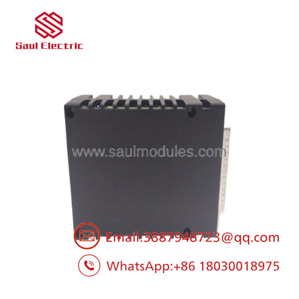
- IS220PVIBH1A
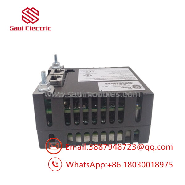
- IS220PVIBH1A
Frequently Asked Questions (FAQ)
Can I hot-swap this vibration pack while the turbine is operating online?
Yes, if your Mark VIe system uses a dual or Triple Modular Redundant (TMR) I/O configuration where multiple packs are cross-voted on a TVIB terminal board, you can swap a single pack while online. However, if the system is configured in a simplex layout, pulling the pack will immediately drop all vibration telemetry. This will cause the primary controller to initiate an emergency shutdown (ESD) due to the loss of critical machine protection data. Always verify your redundancy model before proceeding.
What is the specific role of the 2 Keyphasor inputs on this board?
The Keyphasor inputs accept pulses from once-per-revolution phase reference sensors. The uses these timing signals to correlate physical shaft angles with raw vibration waveforms. This allows the internal digital signal processor to compute phase angles, track synchronous 1X/2X vectors, and generate orbital diagnostic plots vital for identifying shaft misalignment or mechanical unbalance.
Does the require manual calibration after physical mounting?
The pack itself does not require manual component calibration because it utilizes automated self-correcting 24-bit analog-to-digital converters. However, you must ensure that the correct sensor scaling factors (e.g., 200 mV/mil for standard 8mm proximity probes) and specific alert/trip thresholds are pushed down to the pack from the master controller via ToolboxST after installation.
What should I check if a “Sensor Bias Fault” diagnostic alarm occurs?
A sensor bias fault indicates that the DC voltage returning from the proximity probe or accelerometer has drifted outside the hardware’s expected linear range (typically between −4 V DC and −16 V DC for standard proximity systems). If this alarm activates, verify the physical probe gap distance at the machine case, check the extension cable connectors for moisture contamination, and confirm the terminal board supply voltage configuration is correct.
Why choose a New Surplus over standard factory lead times?
Procuring a New Surplus module allows your facility to bypass extended factory production backlogs, which can disrupt maintenance schedules during critical plant outages. These genuine OEM modules are kept in climate-controlled environments and undergo complete structural, continuity, and high-throughput network routing verification to ensure out-of-the-box reliability.



 Start Chat


