





Description
Key Technical Specifications
| Parameter | Value |
|---|---|
| Manufacturer | GE Energy |
| Model Number | IS230JPDGH1B |
| Product Type | 28 V DC Power Distribution Module |
| Platform | Mark VIe / Mark VIeS Speedtronic |
| Primary Function | DC power distribution for control system I/O |
| Input Voltage | Dual redundant 28 V DC (24–30 V DC operating range) |
| Output Channels | 16 individually fused 28 V DC outputs |
| Protection | Replaceable fuse for each output channel |
| Isolation | 2,500 VAC RMS field-to-backplane isolation |
| Mounting | 35 mm DIN rail |
| Communication | IONet status monitoring |
| Operating Temperature | -40 °C to +70 °C |
These specifications are consistent across multiple industrial automation references for the IS230JPDGH1B module.
Product Introduction
The GE IS230JPDGH1B is a 28 V DC Power Distribution Module designed for the GE Mark VIe and Mark VIeS Speedtronic control platform. It distributes redundant DC control power to I/O packs, terminal boards, field transmitters, and other critical control hardware while providing individual fuse protection for each branch circuit.
The module mounts directly on a DIN rail and helps maintain system availability by supporting redundant power sources. Before installation, verify the input voltage, terminal configuration, and associated power distribution architecture to ensure compatibility with the existing control cabinet.
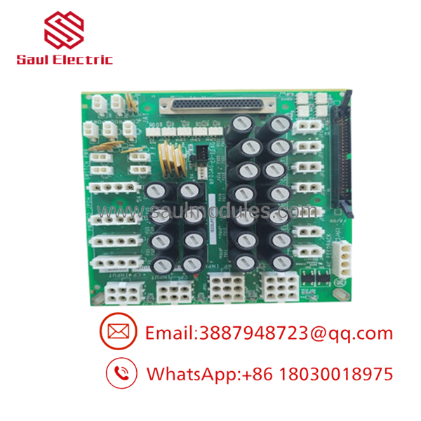
- IS230JPDGH1B
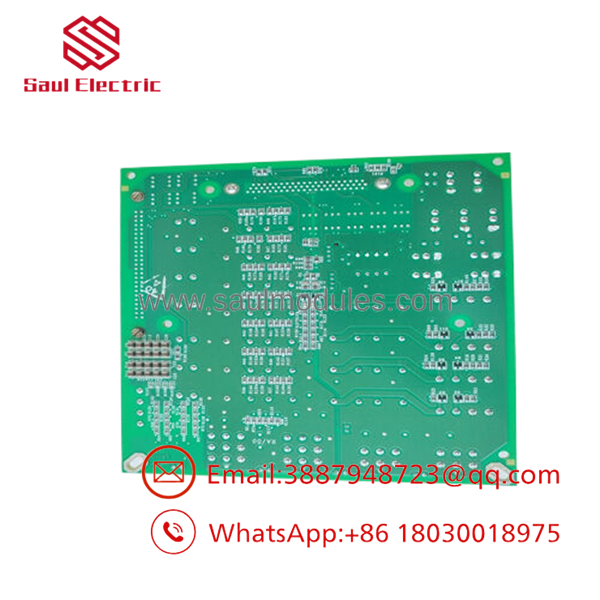
- IS230JPDGH1B
Troubleshooting Quick Reference
| Symptom | Possible Cause | Relevance to this Part | Quick Check Method | Recommendation |
|---|---|---|---|---|
| Multiple I/O packs lose power | Incoming 28 V DC supply failure | ❌ Low | Measure both redundant DC inputs with a calibrated multimeter | Verify power supplies before replacing the module |
| One field device loses power | Blown branch fuse | ✅ High | Check continuity of the individual output fuse | Replace the fuse after eliminating the fault |
| One output channel dead | Short circuit on field wiring | ✅ High | Disconnect the load and measure output voltage | Repair field wiring before replacing hardware |
| Fuse repeatedly opens | Downstream overload | ❌ Low | Measure branch current and inspect connected devices | Remove overload before installing a new fuse |
| Low output voltage | Loose terminal connection | ✅ Medium | Tighten power terminals and inspect for overheating | Repair the connection and retest |
| Power status alarm in Mark VIe | Input redundancy lost | ✅ High | Verify both redundant power feeds and IONet diagnostics | Restore redundant supply operation |
| Physical overheating | Loose power terminals or excessive current | ✅ Medium | Inspect terminals for discoloration using thermal inspection | Correct wiring and torque to specification |
Technical Note: The IS230JPDGH1B is a passive power distribution module and has a relatively low hardware failure rate. Most reported faults originate from blown fuses, overloaded field circuits, damaged wiring, or loss of one redundant DC supply.
Frequently Asked Questions (FAQ)
Q1. What is the used for?
The distributes redundant 28 V DC control power throughout a GE Mark VIe or Mark VIeS cabinet. It supplies power to I/O packs, terminal boards, sensors, and field devices while protecting each output with an individual fuse.
Q2. Does this module provide redundant power?
Yes.
It accepts two independent DC power inputs. If one supply fails, the remaining source continues supplying the control system, reducing the chance of a complete shutdown.
Q3. Can I replace a blown fuse without replacing the module?
Usually yes.
A blown fuse generally indicates a downstream wiring fault or overloaded device. Find and correct the root cause before installing a replacement fuse, or the new fuse will likely fail immediately.
Q4. Does this module require firmware?
No.
The is a hardware power distribution module. It does not require firmware updates, although the control system can monitor power and fuse status through the Mark VIe architecture.
Q5. Why is New Surplus inventory less expensive than factory inventory?
Most New Surplus inventory comes from canceled turbine projects, unused OEM spare inventories, or maintenance stock. These units have not been placed into production service but are no longer part of normal manufacturing.
Q6. What should I verify before ordering?
Verify:
- Exact model number ()
- Mark VIe or Mark VIeS compatibility
- Input voltage requirements
- DIN rail installation
- Terminal block compatibility
- Number of required output circuits
- Existing cabinet wiring configuration
Q7. What warranty is typically available?
Most industrial automation suppliers provide a 12-month warranty for verified New Surplus or professionally tested modules. Request inspection records, serial-number photographs, and functional test documentation before shipment.
Quality Inspection & Testing SOP
1. Inbound Inspection & Traceability
- Verify OEM labels, serial numbers, and hardware revision.
- Inspect the housing, DIN rail clips, terminals, and fuse holders.
- Check for corrosion, overheating, cracked insulation, or repair evidence.
- Record serial numbers for complete traceability.
2. Live Functional Testing
- Install the module in an in-house GE Mark VIe test cabinet.
- Apply redundant 28 V DC inputs.
- Verify automatic transfer between redundant power sources.
- Test every fused output channel under simulated load.
- Monitor voltage stability during a continuous 24-hour load test.
- Generate a documented functional test report.
- Test photos and videos are available upon request.
3. Electrical Parameter Testing
- Perform insulation resistance testing using a 500 V Megger where applicable.
- Verify protective ground continuity.
- Measure input and output voltages using a calibrated Fluke 115 digital multimeter.
- Verify fuse continuity and voltage drop across each output circuit.
4. Firmware & Configuration Verification
- Confirm hardware revision and identification labels.
- Verify terminal block compatibility.
- Document all inspection results before shipment.
5. Final QC & Packaging
- QC inspector approval.
- Package in an ESD-safe bag.
- Protect with anti-static foam, bubble wrap, and a heavy-duty corrugated carton.
- Apply a dated QC Passed label.
Technical Pitfalls & Survival Guide
❗ Don’t Replace the Module Until You’ve Checked the Fuse
I’ve seen technicians replace an entire JPDG module because one output stopped working.
The actual problem was a single blown branch fuse caused by a pinched field cable.
❗ Verify Both Redundant Power Supplies
One failed DC power supply can generate alarms even though the turbine continues operating.
Measure both inputs before assuming the power distribution board has failed.
❗ Calculate Total Load Current
Adding another field device without checking the power budget is a common mistake.
Leave at least a 20% current margin on the DC supply to prevent nuisance trips during startup.
❗ Tighten High-Current Terminals Correctly
Loose power terminals create heat long before they create alarms.
Inspect terminals for discoloration and use the OEM torque specification during installation.
❗ Electrostatic Discharge (ESD)
Always wear a grounded wrist strap.
I once watched a technician troubleshoot a power distribution issue for hours, only to discover that static discharge had damaged the module’s monitoring circuitry while the power distribution itself still appeared normal. ESD damage doesn’t always cause an immediate failure.
Keep these checks in mind and you’ll eliminate most DC power distribution problems, avoid unnecessary module replacements, and reduce unplanned turbine downtime.


 Start Chat


