





Description
Key Technical Specifications
| Parameter | Value |
| Functional Acronym / Layout | AEBM / AEBMH1A (Advanced Controller Block) |
| Hardware Revision Rating | Revision H1AJD (Group 1, Version JD) |
| System Compatibility | GE Mark VIe Distributed Control System (DCS) / Turbine Panels |
| Primary Base Structure | Integrated high-thermal-efficiency aluminum alloy heat sink module |
| Communication Protocols | Modbus TCP/IP, Modbus RTU, CANopen, and serial extensions |
| Connection Ports | RS-485 interfaces, CAN bus junctions, and multi-mode Ethernet links |
| Operating Supply Input | Nominal 24 V DC system power loop (Low current draw) |
| Execution Performance | High-speed real-time logic parsing with hot-standby redundancy tracking |
| Operating Temperature | −40 to +85 °C (−40 to 185 °F) wide-range industrial threshold |
| Physical Dimensions | 173 mm \times 112 mm \times 13 mm (6.81 in \times 4.41 in \times 0.51 in) |
| Net Hardware Weight | 0.26 lbs (0.12 kg) |
Product Introduction
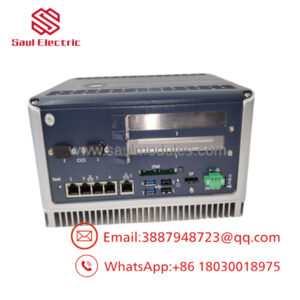
The GE IS400AEBMH1AJD is a high-reliability digital controller and communication interface module engineered for General Electric’s PACSystems Mark VIe and Mark VIeS distributed control architectures. Operating as a critical link in heavy-duty turbine control loops, power generation facilities, and petrochemical operations, this board processes sophisticated, real-time communication algorithms while linking field buses into the primary control processor networks.
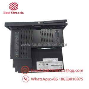
A key structural feature of the IS400AEBMH1AJD is its factory-integrated, high-grade aluminum alloy heatsink module base. Because it is designed to operate in high-temperature turbine enclosures with ambient limits spanning −40 to +85 °C, the mechanical profile utilizes passive thermal dissipation instead of fans. This eliminates mechanical wear points and protects the board’s internal components against thermal tracking shifts, voltage spikes, and conductive dust accumulation.
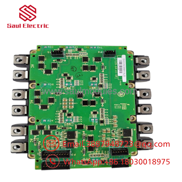
- IS400AEBMH1AJD
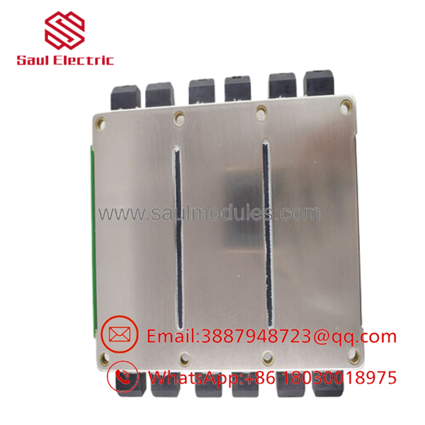
- IS400AEBMH1AJD
Installation & Field Swap Guide
Stage 1: Pre-Installation Preparation (Estimated Time: 15 minutes)
- ⚠️ Safety First: Coordinate with the main control operators before beginning work. Place any hot-standby backup processor systems or safety interlocking communication links handled by this module into a secure override mode. Pulling a live interface board can cause an immediate system trip or data network freeze.
- Tools Required: Grounded static-dissipative ESD wrist strap, non-conductive safety pad, metric nut drivers, and a calibrated digital multimeter.
- Firmware Verification: Verify your active project profiles, communication node numbers, and network configuration pathways inside the ToolboxST software workspace before beginning physical work.
Stage 2: Removing the Faulty Card Unit (Estimated Time: 10 minutes)
- Securely connect your ESD grounding wrist strap to a bare metal terminal block on the panel frame.
- Carefully label and disconnect all data buses, CAN networks, RS-485 plugs, and Ethernet links from the terminal interfaces.
- Loosen the physical perimeter mounting bolts or clips locking the integrated alloy heatsink plate down onto the chassis frame rail.
- ⚠️ Note: Pull the card out straight along its orientation track. Do not tilt or twist the unit, as this can score the internal multi-layer traces or distort localized connector interfaces. Place the module directly inside an ESD shielding bag.
Stage 3: Installing the New Controller Module (Estimated Time: 10 minutes)
- Extract the new IS400AEBMH1AJD module from its static wrap, holding it strictly by the metal cooling fins or casing edges.
- Check that all physical layout profiles, hardware components, and the full version suffix (
H1AJD) match the card being replaced. - Position the card onto the mounting standoff array. Ensure the integrated backplate seats flush against the panel base to allow correct heat transfers.
- Torque down the perimeter mounting screws evenly to lock down structural stability and establish a solid chassis ground.
- Reconnect all communication lines, network leads, and the 24 V DC supply wires to their designated ports.
Stage 4: Power-On Validation & Network Sync (Estimated Time: 15 minutes)
- Clear the panel area of any loose maintenance equipment, then re-energize the primary 24 V DC system breaker line.
- Track the module initialization cycle. The primary power and operational status LEDs should stabilize to green. If a fault light illuminates, check your local bus connection parameters.
- Access your ToolboxST software terminal. Verify that the newly installed controller establishes communication with the network and loads its active operational image from the host system without configuration errors.
- ⚠️ Troubleshooting Note: If the system returns an immediate network fault or mismatched hardware alert, open the active error log. Ensure the full structural suffix matching matrix in your configuration software is updated to match the physical
H1AJDtracking profile.
Frequently Asked Questions (FAQ)
What specific purpose does the integrated alloy heatsink serve on this module?
The high-performance micro-circuit arrays on the IS400AEBMH1AJD process heavy communication flows continuously, which generates localized thermal energy. The integrated aluminum alloy heatsink distributes this heat away from sensitive electronic components using passive convection. This design allows the board to operate reliably up to 85 °C in sealed cabinets without requiring active cooling fans that could suck in ambient dust or moisture.
Sumset
Can the electronic board section be separated from the underlying metal heatsink base?
The circuit board layer and the structural thermal management plate are engineered and assembled as a single, calibrated unit at the factory. Attempting to detach the PCB from its heatsink base can warp the board, disrupt internal trace pathways, or damage the thermal interface material between components. This compromises the module’s cooling efficiency and voids its operational rating.
Does this module automatically handle redundant hot-standby architectures?
Yes. When deployed within a Mark VIe or Mark VIeS multi-controller structure, the module natively supports dual or triple redundant configurations. If a primary interface card encounters a problem or drops a packet loop, the network automatically switches tracking paths to a hot-standby module within milliseconds, ensuring uninterrupted operations.
What communication protocols can be initialized on this card simultaneously?
Depending on how the module is configured in your ToolboxST engineering workspace, the card can process multiple data paths at once. It supports industrial protocols including Modbus TCP/IP over its high-speed Ethernet links, alongside CANopen and Modbus RTU via its isolated RS-485 and serial bus interfaces.
Since active production has moved to newer control iterations, what is the status of this stock?
This item is available as a verified New Original / New Surplus component sourced from climate-controlled industrial spare parts pools and canceled plant modernization packages. Because factory production of these specific legacy generations has ceased, they are increasingly difficult to obtain via standard distribution channels. We run every module through strict physical inspections and component continuity checks to ensure full out-of-the-box reliability, and back each unit with our complete 1-year independent operational warranty.

 Start Chat


