





Description
Product Introduction
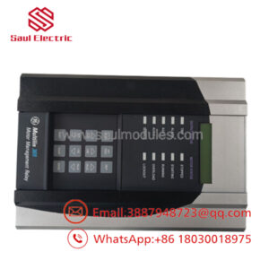
The GE Multilin MIVII1000E00HI00 is an internal processing and signal-conditioning module designed specifically for the MIV II series of voltage, frequency, and motor protection relays. Built for utility substations, heavy industrial plants, and generation facilities, this internal electronics unit executes microsecond-level fault detection to trip breakers before equipment damage occurs.
Unlike general-purpose control boards, the MIVII1000E00HI00 is built to withstand high electro-magnetic interference (EMI) and extreme transient voltage spikes common in medium-voltage power distribution switchgear. Replacing a faulty module with a tested unit allows plant engineers to restore complete relay protection on critical feeder and motor circuits without replacing the entire switchgear door door-mounted enclosure.
Key Technical Specifications
| Parameter | Value |
| Relay Family | GE Multilin MIV II Series |
| Functionality | Voltage / Frequency / Over-Under Current Trip Logic Processing |
| Control Voltage Range | Standard Substation DC / AC Auxiliary Input Limits |
| Operating Temperature | -20°C to +60°C (-4°F to 140°F) |
| Isolation Rating | 2.0 kV AC dielectric withstand for 1 minute |
| Mounting Style | Internal chassis slot rack / modular sub-assembly |
| Output Contacts | Solid-state drive logic to heavy-duty trip relay contacts |
| Conformal Coating | Standard industrial environment coating for harsh sulfur/humidity exposure |
Application Scenarios & The “Trench” Experience
A steel mill was running a critical 4.16kV main rolling motor when a sudden utility brownout caused an undervoltage trip fault. Upon clearing the line fault, the maintenance crew discovered the MIV II relay on the motor control center (MCC) bucket was completely dead—no display, no trip coil signal. Without motor protection online, safety standards prohibited restarting the primary drive, causing a loss of $15,000 per hour in idle mill downtime.
- Medium-Voltage MCC Protection – Monitoring voltage balance, phase sequence, and frequency limits on heavy industrial induction motors.
- Substation Feeder Automation – Interfacing potential transformer (PT) inputs to execute automatic load shedding during frequency drops.
- Co-generation & Backup Power Systems – Preventing islanding by detecting grid voltage loss and signaling intertie breakers to open instantly.
- Mining & Heavy Processing Facilities – Providing reliable fault-isolation logic in high-vibration, dust-heavy substation environments.
Field Case Study
A chemical processing plant encountered a failure in the trip control section of an aged MIV II protection relay controlling a major compressor drive. The OEM lead time for a complete new-generation relay retrofit involved 4 weeks for panel redesign and wiring drawing updates. We dispatched a fully bench-tested MIVII1000E00HI00 sub-assembly overnight. The lead electrician pulled the defective internal assembly, installed the replacement, verified trip contacts using a secondary injection test set, and restarted the line by mid-afternoon.
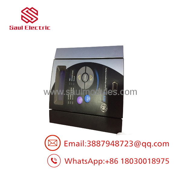
MIVII1000E00HI00
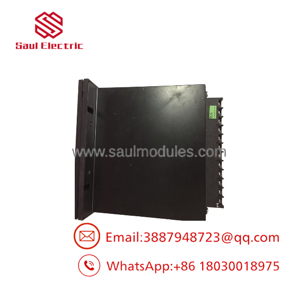
MIVII1000E00HI00
Transparency SOP: Quality Assurance & Testing
Protective relays are safety devices; they cannot fail when a real fault hits the bus. We put every GE Multilin sub-assembly through rigorous verification.
- Inbound Visual & Component Audit: Inspecting trace health, checking for swollen capacitors, cracked solder joints, or heat discoloration around power components.
- Auxiliary Power Rig Testing: Powering up the assembly on a specialized test bench to verify internal DC bus voltage regulation.
- Signal Injection Verification: Injecting precise AC/DC analog values to check trigger levels, operational thresholds, and trip timing accuracy.
- Relay Contact Continuity & Response: Measuring contact bounce, closing speeds, and isolation resistance under simulated trip conditions.
- Final Environmental Pack: Sealing in anti-static ESD barrier packaging with fresh desiccant prior to dispatch.
The Veteran’s Tech Trap Guide (Crucial Value-Add)
- ⚠️ Do Not Swap Internal Cards Under Power: Never attempt to pull or insert this internal sub-assembly while the auxiliary power supply or current/voltage transformer inputs are energized. Secondary voltage from PTs or open CT circuits can cause flashover and destroy the card instantly.
- ❗ Verify Model Option Codes: The string “1000E00HI00” specifies exact internal options, control voltage requirements, and communication protocols. Double-check all characters against your failed board’s serial tag to ensure full cross-compatibility before racking it in.
- ⚠️ Check External PT/CT Circuits: If the original board suffered a burned input circuit, verify that external Potential Transformers (PTs) or Current Transformers (CTs) didn’t flash over. Connecting a fresh board to a shorted instrument transformer circuit will destroy the replacement card immediately.
- ❗ Test with Secondary Injection Before Energizing: After installing the board, perform a quick secondary injection test on the relay to confirm trip settings match plant protection coordination curves before re-closing the main breaker.
Frequently Asked Questions (FAQ for Conversion)
Q: Is the GE MIVII1000E00HI00 a complete standalone relay or an internal board?
A: Part number MIVII1000E00HI00 typically designates the specific hardware configuration breakdown (internal electronics module/processor chassis) within the GE Multilin MIV II family.
Q: Can I load my existing protection settings into this replacement module?
A: Yes. Once installed, protection parameters can be loaded via the front-panel interface or GE Multilin software using the stored setpoint documentation from your plant’s engineering files.
Q: Is this GE Multilin MIV II module still supported by the original manufacturer?
A: The MIV II series is largely discontinued/legacy status by GE. Direct factory replacements are often obsolete, making bench-tested new surplus or refurbished units the fastest solution to avoid panel modification costs.
Q: What warranty comes with this surplus GE protection module?
A: Every unit shipped includes a comprehensive 12-month replacement warranty, ensuring it functions strictly to original technical specifications.
Q: How do I know if the failure is in this module or the relay power supply?
A: If the relay display is completely dead and auxiliary power is present at the back terminals, the internal power supply or main processing board (MIVII1000E00HI00) is the primary failure point.


 Start Chat


