





Description
Technical Specifications Matrix
| Parameter | Specification Detail |
|---|---|
| Windings Config | 2 Windings per Phase (W2) |
| Phase Current Inputs | 1 A AC RMS (P1) secondary rating |
| Ground Current Inputs | 1 A AC RMS (G1) secondary rating |
| Power Supply Operating Range | 90 to 300 VDC |
| Analog I/O Array | 4 channels of 4 to 20 mA (or 0 to 1 mA) Transducer I/O (A) |
| Asset Analytics | Integrated Transformer Hottest-Spot, Loss-of-Life, and Aging Factor calculation (L) |
| Protection Elements | Percent Differential, Restrained Ground Fault, Overexcitation (V/Hz), Overcurrent, Frequency |
| Isolation / Dielectric | 2000 V AC for 1 minute (inputs, outputs, power rails) |
| Output Relay Configuration | 1 Fast Solid-State, 7 Electromechanical Form-C relays |
| Communication Array | 1 Front RS-232, 2 Rear RS-485 / RS-422 ports (Modbus RTU / DNP3.0 protocols) |
| Enclosure Rating | IP40 (Front bezel), IP20 (Rear terminals), standard 19-inch rack draw-out case |
| Operational Limits | −40 to +60°C (−40 to +140°F) ambient environment |
Product Introduction
The GE Multilin SR745-W2-P1-G1-HI-A-L-R is a highly configurable, multi-processor-based protection relay designed for the comprehensive management of small, medium, and large utility power transformers. This specific full-featured configuration is tailored for two-winding step-up or step-down sub-transmission and industrial transformers (W2). It incorporates sophisticated percentage differential protection alongside high-speed fault containment logic to prevent catastrophic failure while eliminating nuisance trips caused by magnetizing current inrush or heavy through-fault current saturation.
Power Duke
This advanced revision features integrated Analog Transducer I/O boards (A) alongside the Loss-of-Life hardware package (L), which dynamically measures transformer health parameters based on IEEE Standard C57.91. By monitoring real-time loading profiles and ambient thermal indicators, the relay computes actual insulation aging and cumulative loss-of-life variables. The high control power module (HI) allows smooth operation across volatile utility control batteries or standard AC power feeds, while the 1A current inputs ensure precision compatibility with long-run substation CT instrumentation configurations.
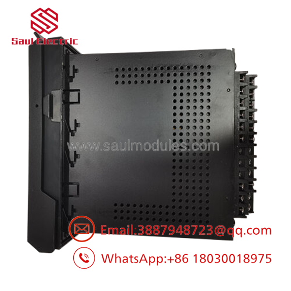
- SR745-W2-P1-G1-HI-A-L-R
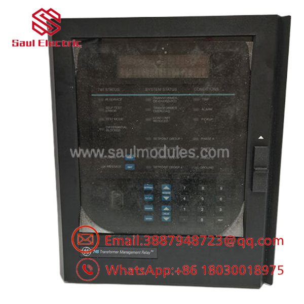
- SR745-W2-P1-G1-HI-A-L-R
Installation & Configuration Guide
Stage 1: Pre-Installation Preparation
- ⚠️ Safety First: The protection relay directly triggers circuit breaker trip coils. Never bridge or manipulate current transformer (CT) secondary circuits while they are open and energized. High inductive voltages will generate immediately, creating lethal shock and flash hazards. Short-circuit all secondary CT paths at the test switch blocks before disconnecting or swapping out this relay.
- Tools Required: Calibrated torque screwdriver (cross-head), CT shorting keys/jumpers, digital multimeter, PC loaded with EnerVista 745 Setup software, RS-232 serial hookup cable.
- Backup Settings: Connect to the existing unit via the front RS-232 interface port using the EnerVista 745 software. Create an immediate file backup of all active setpoints, customized FlexLogic™ equations, phase CT mismatch compensation values, and historic event logs.
Stage 2: Extracting the Relay from the Chassis Cradle
- Switch the internal current terminal test blocks into their safe “Short-Circuit” position to isolate the relay’s measuring inputs.
- Disengage the secondary auxiliary power distribution breaker to kill incoming line voltage to the unit.
- Open the protective clear acrylic front access door on the standard 19-inch chassis.
- Loosen the integrated draw-out thumbscrews on the inner metal frame faceplate.
- Firmly grasp the built-in draw-out handles, pull them outward symmetrically to unlatch the internal rear terminal block friction blocks, and pull the core relay module straight out of its stationary case cradle.
Stage 3: Installing the New Module
- Verify the replacement unit’s model label matches exactly: SR745-W2-P1-G1-HI-A-L-R.
- Align the core card runner blocks with the inner tracks of the stationary chassis case.
- Push the module smoothly and firmly straight backward into the chassis cradle until the rear self-aligning terminal blocks engage with their stationary terminal companions.
- Swing the latching handles shut and secure the faceplate thumbscrews to anchor the chassis block against thermal expansion and structural vibration.
- Remove the shorting elements from the current loop test blocks only after the relay has been locked down and power verified.
Stage 4: Commissioning & Startup Testing
- Re-engage the master protection power breaker to feed the unit via the high power rail (
HI). - Observe the front display. The unit should pass its internal power-on self-test, and the green In Service LED indicator should illuminate steadily.
- ⚠️ Troubleshooting: If the amber Self-Test Error or red Relay Fault light lights up, use EnerVista to view the diagnostic logs. This usually signals a loose terminal connection block or a problem with an unmapped analog loop assignment.
- Establish an active link to the relay from your laptop via the front panel connection port, verify the target firmware build, and download your stored configuration setpoint matrix directly to the replacement module.
Frequently Asked Questions (FAQ)
What do the codes “A”, “L”, and “R” represent in this specific part number?
- A: Indicates the factory inclusion of 4–20 mA (or 0–1 mA) analog inputs and outputs, allowing the relay to ingest transducer variables like oil levels or gas pressures.
- L: Designates the Loss-of-Life module, which computes transformer insulation deterioration, hottest-spot temperatures, and cumulative asset fatigue over time.
- R: Signifies advanced protection configurations, including dedicated Restricted Earth Fault (REF) protection metrics and adaptive harmonic wave restraint loops.
Can I insert a 1A rated relay into a circuit that uses 5A CT secondaries?
No, you cannot. This relay is hardwired and calibrated specifically for 1A phase and ground CT inputs (P1 and G1). Connecting a 5A current loop to these terminals will saturate the input sensing electronics almost immediately during load spikes, leading to incorrect metering data, hardware faults, or internal circuit failure due to excessive thermal loading.
Why is this unit sold as a “New Surplus” legacy model?
The Multilin 745 protection line is a highly trusted legacy architecture developed by GE Grid Solutions, which has since been succeeded by the modern Multilin 845 system. Because GE no longer manufactures these units, our inventory consists of New Surplus / New Original units. These are pristine, unused warehouse spares preserved from plant modernization rollouts or system engineering reserves, enabling operators to swap matching hardware configurations instantly without carrying out complicated site re-engineering or rewiring.
How does the adaptive harmonic restraint function handle transformer inrush?
When a large power transformer is first energized, it pulls a massive magnetizing inrush current that can look exactly like an internal phase fault to a standard differential relay. The SR745 resolves this by checking for a high content of second and fifth harmonics inside the waveform. If found, the relay automatically holds back its percent differential trip command for a brief period, preventing annoying false trips during standard network switching procedures.



 Start Chat


