





Description
Product Introduction
The GE Multilin UR6CH is the primary 19-inch rack-mount 4RU chassis designed to house GE’s Universal Relay (UR) platform modules. Serving as the mechanical and electrical foundation for protective relays such as the C60, G60, L90, and T60, this main chassis contains the high-speed passive backplane that routes power, inter-module communications, and signal buses between CPU, CT/VT, power supply, and I/O cards.
Unlike standalone, fixed-geometry protection relays, the UR6CH chassis architecture gives utility and industrial protection engineers complete modularity. When a backplane trace degrades or physical rack ear damage occurs on a critical substation bay, replacing the UR6CH chassis allows maintenance crews to swap over existing working modules without scrapping expensive CPU or DSP cards.
Key Technical Specifications
| Parameter | Value |
| System Compatibility | All GE Multilin Universal Relay (UR) Family Modules |
| Form Factor | Standard 19-inch Rack Mount (4RU Height) |
| Slot Capacity | Up to 8 or 14 module slots (depending on backplane revision & card size) |
| Backplane Type | Multi-layer PCB with high-speed serial bus & CT/VT terminal pass-through |
| Grounding | Heavy-duty copper earth ground stud on rear chassis panel |
| Mounting Options | Front panel rack mount / optional wall mount brackets |
| Operating Temperature | -40°C to +60°C (-40°F to 140°F) |
| Enclosure Material | Heavy-gauge aluminum/steel anti-corrosion treated frame |
Application Scenarios & The “Trench” Experience
A 115kV substation feeder tripped on a bus fault during a severe summer thunderstorm. During emergency troubleshooting, a field technician discovered that a flashover on an external CT line had arc-tracked across the rear terminal block of the L90 line differential relay, scorching the chassis backplane. While all internal microprocessor cards survived intact, the damaged backplane rendered the relay unusable. Finding an exact UR6CH chassis replacement was critical to restoring line protection before peak load hours.
- Substation Transmission & Distribution Bays – Housing modular line differential (L90), transformer (T60), and bus (B90) protection systems.
- Industrial Generator Control Panels – Mainframe chassis for G60 generator protection units in thermal and hydroelectric plants.
- Large Motor Protection Centers – Enclosing M60 motor protection modules in heavy industrial processing facilities.
- Utility Control Room Racks – Providing standardized 4RU hardware footprints across entire substation relay bays.
Field Case Study
During a scheduled station maintenance window, a utility crew needed to replace a physically damaged rack enclosure on a critical transmission tie-line relay. Instead of taking the line down for days to configure a brand-new relay from scratch, they sourced a verified UR6CH chassis. The protection team unbolted the damaged chassis, mounted the replacement UR6CH into the 19-inch rack, transferred the existing CPU, power supply, and CT/VT modules into their identical slot locations, and completed end-to-end testing in under three hours.
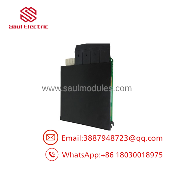
UR6CH
Transparency SOP: Quality Assurance & Testing
Chassis backplanes must maintain flawless signal integrity across high-speed digital buses. Every GE Multilin chassis undergoes a strict physical and electrical verification SOP.
- Inbound Structural & Visual Audit: Inspecting rack ears, chassis alignment, mounting screw threads, and checking rear terminal blocks for heat stress or arc tracking.
- Backplane Pin & Socket Inspection: Examining every female backplane connector pin under magnification for bends, corrosion, or recessed contacts.
- Power Rail & Continuity Testing: Measuring trace resistance across all internal backplane power distribution tracks and signal buses.
- Live Card Insertion & Handshake Test: Populating the chassis with a test set of UR cards (Power Supply, CPU, I/O) to verify clean bootup, module indexing, and inter-card communications.
- ESD Cleaning & Secure Packaging: Cleaning internal card guides and wrapping the chassis in heavy-duty ESD protective wrap with foam edge blocks for safe transport.
The Veteran’s Tech Trap Guide (Crucial Value-Add)
- ⚠️ Match Your Card Slot Layout: While all chassis share the standard 4RU frame, GE manufactured different backplane variations (e.g., standard vs. redundant power supply backplanes, different CT/VT module alignments). Verify your exact rear terminal layout and card slot positions before transferring modules.
- ❗ Never Force a Card into the Backplane: UR series cards should slide smoothly along the internal plastic guides and seat with firm thumb-latch pressure. If a card stops short, do not force it—a bent backplane pin will short out the entire 5V/12V logic bus and destroy adjacent modules upon power-up.
- ⚠️ Ground the Chassis Frame First: Before landing any field CT/VT wiring or applying power to the installed modules, connect a solid, low-impedance earth ground lead to the main copper ground stud on the back of the chassis. High static charges on ungrounded frames can corrupt CPU memory during card insertion.
- ❗ Label Every Module Position: Before gutting a damaged chassis, label every card (Slot A through Slot M) clearly. Installing a CT/VT card or digital I/O card into the wrong backplane slot location on reassembly will cause startup self-test failures or incorrect trip logic execution.
Frequently Asked Questions (FAQ for Conversion)
Q: Does the chassis come equipped with internal cards or a power supply? A: No. The designates the bare 19-inch 4RU enclosure and passive backplane board assembly. Power supply units, CPU modules, CT/VT cards, and digital I/O boards are installed separately based on your specific relay model code.
Q: Can I replace a chassis without re-licensing or re-flashing software? A: Yes! Because the system software, IP addresses, and protection setpoints reside entirely on the CPU module (Slot B/C) and setting files, swapping the physical chassis requires no software reconfiguration.
Q: Are there different depth options for the chassis? A: The standard uses GE’s standard deep 19-inch rack footprint. Verify your rear cabinet depth clearance to ensure proper space for field terminal wiring bends and CT shorting blocks.
Q: What warranty coverage do you provide on this UR chassis? A: Every chassis—whether factory-sealed new surplus or bench-tested refurbished stock—is backed by our full 12-month functional replacement warranty.
Q: What is the fastest way to verify if my current relay failure is the chassis backplane or an individual card? A: If multiple cards in different slots simultaneously report communication faults, lose DC power rails, or fail self-tests, the backplane traces or connector pins on the chassis are the primary failure suspects.



 Start Chat


