





Description
Key Technical Specifications
| Parameter | Specification / Value |
| Processor Speed | 500 MHz high-speed 32-bit embedded RISC architecture |
| Ethernet Interfaces | Redundant 100Base-FX Multi-Mode Fiber Optic (ST ports) |
| Fiber Optical Wavelength | 1300 nm nominal wavelength profile |
| Serial Communications | 1 × isolated RS485 port, 1 × front-panel RS232 programming port |
| Network Protocols | IEC 61850, DNP3 TCP/IP, Modbus TCP/IP, IEEE C37.94 |
| Logic Engine Support | FlexLogic programmable execution paths (up to 1024 lines) |
| Event Recorder Size | 1024 time-tagged chronological sequence logs (0.5 ms resolution) |
| Oscillography Capture | 64 samples per power cycle, extended transient memory allocation |
| Internal Power Draw | < 15 W continuous draw from main system backplane |
| Cybersecurity Suite | CyberSentry infrastructure encryption alignment |
| Operating Temperature | −40°C to +70°C (−40°F to +158°F) |
| Dimensions | 128 mm W × 55 mm H × 190 mm D (5.0 × 2.2 × 7.5 inches) |
| Net Weight | 0.8 kg (1.8 lbs) |
Product Introduction
The GE Multilin UR9KH serves as the primary processing engine for the modular Universal Relay framework. Housed within a standard slot envelope, this card handles high-speed computational tasks, including vector logic execution and phase angle monitoring, required for substation assets. It aggregates incoming digital sample streams from adjacent CT/VT input modules, comparing network values against user setpoints to trigger trip outputs within milliseconds during fault states.
This specific 9K configuration integrates legacy serial communications with redundant 100Base-FX multi-mode fiber optic network channels. The redundant fiber design isolates critical SCADA telemetry from electromagnetic interference (EMI) and ground loops common in high-voltage environments. Post-2015 production runs also feature an added 10/100Base-T copper interface to allow convenient front or rear laptop links during validation windows without breaking the main optical ring.
【Core Strategy 1: SOP Quality Transparency】
Because a CPU failure can disable protection for an entire substation bay, all surplus UR-9KH cards undergo rigorous logic validation before shipment.
1. Inbound Inspection & Traceability
- Origin Auditing: Hardware revision codes are mapped back to OEM manufacturing batches to identify and reject gray-market variations.
- Component Surface Scan: All surface-mount capacitors, internal clock oscillators, and transceiver headers are inspected under microscope arrays to look for microscopic fractures or thermal drift signs.
- Fiber Port Review: Optical ST barrels undergo fiber-optic scope inspection to ensure the lenses are free of scratches or embedded dust particles.
2. Live Functional Testing
- Chassis Integration: The UR-9KH is slotted into a dedicated multi-slot Universal Relay test chassis equipped with a companion power supply and digital I/O simulator cards.
- Boot-Diagnostic Verification: The unit must execute its full internal RAM/ROM diagnostic routines on startup without throwing hardware fault codes.
- Network Stress Testing: Fiber optic ports are connected to a network loop running continuous, high-packet-rate Modbus TCP and IEC 61850 data streams for 12 hours while checking for dropped packets.
- Environmental Burn-In: The CPU runs inside a thermal test chamber at 60°C for 24 hours to eliminate units susceptible to premature component breakdown under thermal stress.
3. Electrical Parameter Testing
- Backplane Isolation: Ground plane separation is verified using specialized multi-meters to ensure auxiliary supply paths remain fully isolated from the digital communication rails.
- Power Draw Benchmarking: The module’s steady-state current draw is measured to ensure it remains within the standard <15 W operational threshold.
4. Firmware & Configuration Verification
- Firmware Validation: Technicians document the loaded firmware branch (e.g., V7.40 or V5.80) to ensure full compatibility with the buyer’s planned target application.
- Volatile Memory Flush: The CPU’s non-volatile memory is cleared of old site configurations, restoring the core factory network settings.
5. Final QC & Packaging
- ESD Shielding: Handled exclusively at static-safe workstations, the module is placed into sealed ESD shielding bags.
- Transit Protection: The card is packed inside custom-molded foam inserts within a thick, double-wall corrugated shipping box to withstand transport shocks. A verified QC checklist with serial numbers is included in the box.
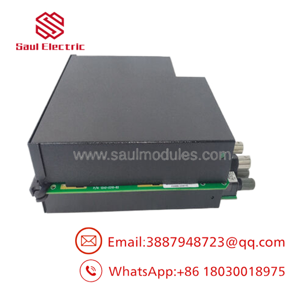
- UR9KH
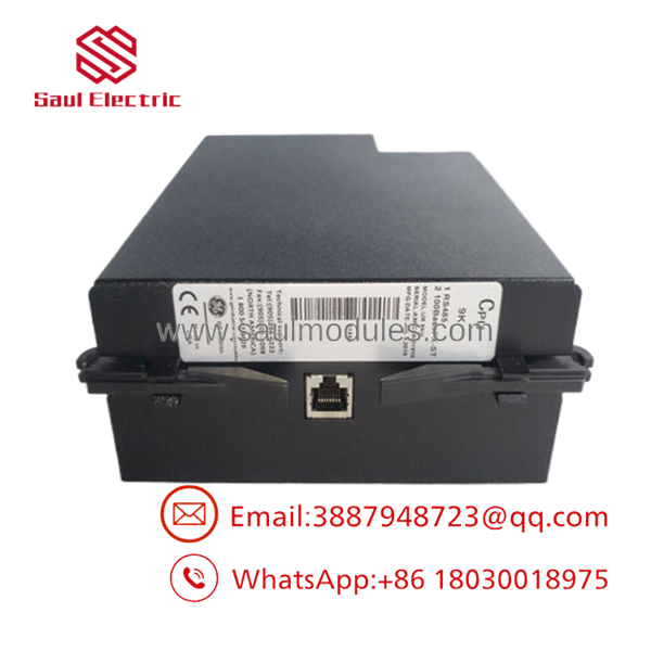
- UR9KH
Installation & Configuration Guide
Stage 1: Pre-Installation Preparation
- Estimated Time: 20 minutes
- ⚠️ Safety First: Disconnect all control power lines feeding the Universal Relay chassis before handling hardware. Verify that all secondary current transformer circuits are safely shorted at the panel terminal block to prevent high-voltage hazards while working near the rack.
- Tools Required: ESD wrist strap, fine flat-head screwdriver, #2 Phillips screwdriver, fiber optic cleaning swabs, and a laptop running EnerVista UR software.
- Data Backup: Connect to the old CPU via the front RS232 port or network connection. Export the complete setpoint database (
.ursfile extension). Record the exact firmware version of the active relay to prevent configuration mismatches later.
Stage 2: Removing the Old Module
- Estimated Time: 10 minutes
- Steps:
- Attach your ESD wrist strap to the panel frame’s ground terminal.
- Label and disconnect the fiber optic cables from the ST ports. Fit protective dust caps over the fiber ends immediately.
- Unplug the RS485 serial communication block harness.
- Loosen the captive Phillips mounting screws located on the top and bottom tabs of the CPU module’s front faceplate.
- Pull the module handle straight out toward you to slide the card out along the interior guide rails.
- ⚠️ Note: Handle the card by its metal faceplate edges. Avoid touching the open backplane pins or surface-mount components.
Stage 3: Installing the New Module
- Estimated Time: 15 minutes
- Steps:
- Ensure the replacement module part number explicitly matches the original
UR-9KHcode. - Slide the module into the targeted slot tracks, maintaining linear alignment until the rear connector seats cleanly into the primary backplane socket.
- Hand-tighten the upper and lower faceplate fastening screws to lock the card flange flat against the chassis edge.
- Clean the optical fiber connectors using specialized fiber swabs, then plug the ST fiber links back into their designated ports.
- Ensure the replacement module part number explicitly matches the original
- Self-Checklist:
- [ ] Flange mounting screws secured flat without gap tolerances.
- [ ] Direct alignment of all field wiring block headers.
- [ ] Removal of temporary external shorting screws after verifying the card is fully seated.
Stage 4: Power-On & Testing
- Estimated Time: 20 minutes
- Power-On Steps:
- Re-energize the main control power supply card of the relay rack.
- Verify that the CPU faceplate status LEDs illuminate properly and the unit boots cleanly without triggering a hardware configuration error.
- Connect your laptop to the diagnostic port. If the replacement card’s firmware version differs from the old module, flash the unit using EnerVista to match your system standard.
- Upload your saved
.ursconfiguration file to restore the relay’s protection setpoints and network addresses. - Check communication to the SCADA master to confirm that data polling over the fiber ring has resumed.
- ⚠️ Troubleshooting Note: If the front panel displays a “Module Incompatible” message, the base firmware version on the CPU does not match the hardware revision indices of the surrounding I/O or CT/VT cards in the rack.
【Core Strategy 2: Technical Pitfall & Survival Guide】
1. Firmware and CT/VT Synchronization Faults
The UR-9KH CPU operates in close coordination with the analog CT/VT input modules in the rack. ❗ A significant gap between module manufacturing dates can trigger system faults. If you pair a brand-new revision UR-9KH CPU with an older generation CT/VT input module, the internal software may flag a hardware incompatibility error upon startup. When replacing a processor card, ensure its firmware version is compatible with the physical revision levels of your existing input and output cards.
2. Optical Fiber TX/RX Cross-Connection Errors
The ST fiber optic ports on the UR-9KH handle separate transmit (TX) and receive (RX) pathways. Crossing these fiber pairs during installation is a common mistake that breaks the communication ring. ❗ If the network link LED remains dark after installation, suspect crossed fibers. Always label your fiber lines clearly before removal. If you encounter communication issues after swapping the card, swap the TX and RX positions to see if the link re-establishes.
3. Settings Loss During Replacement
Because the Universal Relay’s configuration profiles, logic variables, and custom FlexLogic parameters reside directly in the volatile and non-volatile memory of the CPU card itself, swapping this module replaces your entire configuration with factory defaults. Slotted replacement cards do not pull parameters from the backplane. If you power up the system without restoring the .urs backup file via EnerVista, the relay will sit idle and fail to respond to network faults.
4. Backplane Pin Deformation
The UR chassis uses a high-density backplane connector system. If a module is forced into the slot out of alignment, the pins can bend or break. ❗ Never use excessive force to seat a module. If the card flange does not slide completely flush with the external framework under gentle pressure, pull the module back out and inspect the pins using a flashlight. Repairing a damaged backplane requires completely dismantling the relay chassis.
5. Managing Hardware Revisions (Pre vs. Post 2015)
In 2015, GE updated the 9K CPU platform to add a 10/100Base-T RJ45 copper port alongside the existing RS485 and ST fiber ports. While older and newer versions remain functionally interchangeable inside the relay logic, their configuration menus within EnerVista require slightly different settings profiles. Check the bottom-right corner of the module casing for the revision label to ensure your software configuration matches the physical hardware generation.
Frequently Asked Questions (FAQ)
Can I hot-swap the UR-9KH CPU module while the substation bay is live?
No. While the Universal Relay chassis allows hot-swapping for certain digital I/O modules, removing the primary CPU module will instantly take the entire protection rack offline. This drops all active protection algorithms, opens critical monitoring loops, and can cause unpredictable output contact states. Always isolate the primary control power supply before extracting or servicing the CPU card.
What should I do if the new CPU card triggers a “Chassis Mismatch” error on boot?
This error occurs when the hardware layout configuration saved in the loaded setpoint file does not match the physical modules detected in the rack slots. To fix this, connect via EnerVista software, navigate to the “Hardware Options” configuration page, select the “Read Architecture from Relay” command, and resave the updated layout profile to the CPU’s memory.
Does this module support both 1300 nm multi-mode and single-mode fiber infrastructure?
No, the UR-9KH is built specifically for 1300 nm multi-mode fiber networks using standard ST terminations. Connecting this card to a single-mode fiber line will result in high signal attenuation and intermittent communication dropouts. If your site uses single-mode fiber infrastructure, you will need a different CPU module variant or an external single-mode to multi-mode media converter.
How do I clear the previous owner’s security settings if the surplus unit arrives locked?
If a surplus card arrives with an unknown active password configuration that blocks network access, you must establish a direct serial connection through the front-panel RS232 port. Using the EnerVista software utility, execute a hardware factory reset via the clear-memory jumper routine detailed in the master engineering manual to wipe all stored operational security keys.
Is the UR-9KH CPU compatible across all models of the Universal Relay line?
Yes. The UR platform uses a standardized, modular backplane layout. The UR-9KH card can serve as the central processor in a B30 bus differential relay, a C60 breaker manager, a T60 transformer protector, or an L90 line distance relay. The specific identity and protective features of the rack are determined by the .urs configuration file and logic settings you upload to the CPU after installation.


 Start Chat


