





Description
Key Technical Specifications
| Parameter | Specification Value |
| Phase Current Inputs | 5 A nominal secondary transformer rating |
| Control Power Range (HI) | 88–300 VDC, 70–265 VAC at 48–62 Hz |
| Analog Outputs (A20 Suffix) | 8 Channel isolated, 4–20 mA DC configuration |
| Analog Inputs | 4 Channel, 4–20 mA DC differential loops |
| RTD Temperature Inputs | 12 Total (Stator, Bearing, Ambient – 100Ω Pt, 100Ω Ni, 120Ω Ni, 10Ω Cu) |
| Output Relays | 6 Electromechanical Form C relays (Trip, Alarm, Aux blocks) |
| Digital Switch Inputs | 4 Programmable dry contact inputs |
| Protection Elements | Thermal Model (TCU), Stator Differential (87M), Jam, Phase/Ground Overcurrent |
| Sampling Performance | True RMS calculation via multi-point cycle captures |
| Local Interface Display | 40-Character alphanumeric vacuum fluorescent display |
| Serial Ports | 1x Front RS232, 2x Rear RS485 isolated buses |
| Network Protocols | Modbus RTU (up to 19.2 kbps) |
| Event Recorder | Internal non-volatile memory storing up to 256 trailing events |
| Physical Profile Type | Secure draw-out chassis variant with internal shorting mechanisms |
Product Introduction
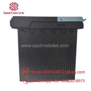
The GE Multilin SR469-P5-HI-A20 is a specialized, microprocessor-based motor management relay engineered to provide advanced protection, control, and monitoring for medium-to-high voltage induction and synchronous motors. Operating as a critical diagnostic hub, it employs a dynamic thermal model with RTD and negative sequence current biasing to calculate real-time Thermal Capacity Used (TCU). It isolates stator breakdown, mechanical jams, stalling, voltage unbalance, and single-phasing conditions before thermal damage compromises stator windings or rotor bars.
The alphanumeric part code layout specifies this unit as a high-tier configuration tailored for drop-in panel deployment. The “P5” designation provides hardware interfaces for 5 A nominal current transformer secondaries, while the “HI” control block ensures compatibility with standard 125/250 VDC or 120/240 VAC station battery supplies. Critically, the “A20” module populates eight independent 4–20 mA analog telemetry loops, allowing real-time tracking of thermal profiles, current demand, and power factors to be mirrored directly to processing DCS and PLC systems without external signal conditioning equipment.
Installation & Configuration Guide
Stage 1: Pre-Installation Preparation (Estimated Time: 15 minutes)
- ⚠️ Safety First: Isolate the target motor breaker and tag/lockout all feed supplies. Never open-circuit an active current transformer. Double-check that your lineup’s CT shorting block keys are fully inserted and screwed down tight prior to messing with rear screw layouts.
- Tools Required: ESD grounded wrist strap, flathead and PH2 screwdrivers, a reliable multimeter, and electrical wire marker sleeves.
- Data Backup: Hook up your laptop to the faceplate RS232 terminal. Use EnerVista 469 Setup utility software to extract and clone the device configuration map (
.469or.X69structure) to guarantee precise duplication of trip settings, cooling constants, and CT parameters.
Stage 2: Removing the Old Module (Estimated Time: 5 minutes)
- Confirm that the external CT shorting rings are pinned down safely.
- Unlatch the protective front faceplate panel handle assembly.
- Pull the locking arm out to mechanically separate the internal terminal connections. Slide the inner draw-out chassis straight forward out of its panel enclosure case.
- If replacing the entire outer case: Label every landing wire on the rear blocks, back out the terminal screws, and unseat the frame retaining nuts.
Stage 3: Installing the New Module (Estimated Time: 10 minutes)
- Fasten your ESD wrist strap before drawing the replacement chassis from its static-shield wrap.
- Verify that the inner secondary automatic shorting bars inside the case frame are clean and functional.
- Align the replacement inner chassis tracking rails inside the perimeter panel case.
- Firmly guide the unit back into place, clicking the draw-out handle locked to complete terminal contact mating.
- Configuration Clone: Energize the control power lines (Terminals 1 and 2). Upload the saved configuration profile using EnerVista software. Verify the calculated unbalance bias K-factor and safe stall parameters align with the specific motor nameplate documentation.
❗ Configuration Check: > [ ] Phase CT ratio scaling matches current plant blueprints.
[ ] Target RTD sensor configuration settings match field sensor types (e.g., Pt100).
[ ] Mechanical engagement handles are fully seated and sealed.
Stage 4: Power-On & Testing (Estimated Time: 10 minutes)
- Confirm the front text panel boots up smoothly and settles with the status LED showing a green “In Service” profile.
- If an automatic fault trip occurs, check the register log to isolate wiring discrepancies across your grounding or phase terminal layouts.
- Activate the local display keypad sequence to monitor actual values and check that static phase and voltage profiles mirror true line expectations.
- Verify serial polling activity across the rear RS485 loop linked to your SCADA architecture.
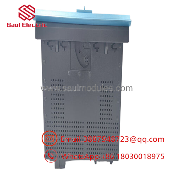
- SR469-P5-HI-A20
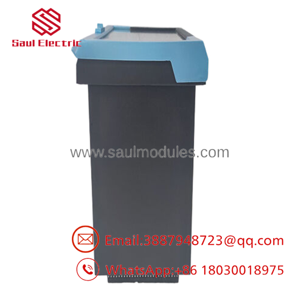
- SR469-P5-HI-A20
Strategic Quality Control & Inspection Process
Given the critical nature of medium voltage motor assets, every legacy or surplus Multilin SR469 relay undergoes a rigorous inspection protocol prior to asset dispatch.
- Inbound Traceability & Mechanical Check: Serial identification structures are vetted to verify asset provenance. We look for physical flaws, including terminal strip fracturing, frame alignment variances inside the draw-out contacts, and screen degradation.
- Primary Injection & Calibration Testing: The relay is placed onto a specialized automated calibration rack. We inject precise phase inputs to verify the measurement accuracy of the 5 A current transformer inputs and check the linearity of the eight 4–20 mA analog output ports across multiple reference points. Trip contact relays are tested under real load profiles to confirm timing metrics down to millisecond accuracy.
- High Voltage Insulation Evaluation: A 500 V Megger insulation resistance check is conducted between internal control terminals and the metal chassis ground points to verify safety and barrier isolation scores remain above 10 MΩ.
- Firmware Compliance & Settings Validation: The firmware build (e.g., V4.0x profile) is verified and updated or downgraded if a customer layout requires precise matching to older legacy network architecture.
- ESD Sealed Packaging: Following technician validation, the relay chassis is locked into place, surrounded by anti-static material wrappers, layered with heavy density foam armor, and sealed inside a rugged transport carton along with its certified inspection pass report.
Frequently Asked Questions
Can I pull the inner chassis of the SR469-P5-HI-A20 while the motor is running?
Technically, the integrated draw-out case construction uses internal shorting bars designed to close the CT loops automatically when the chassis is withdrawn. However, pulling the active protection system while the medium voltage primary circuit is under load leaves the motor running entirely unprotected against stalls, unbalance, or thermal faults. Industry best practice dictates shutting down the motor process before executing a chassis draw-out swap.
What is the specific functional difference between a “-A1” and “-A20” version of this relay?
The difference lies in the analog output current configuration. The “-A1” variant utilizes older 0–1 mA DC analog signal loops. The “-A20” model featured on this page integrates eight industry-standard 4–20 mA DC current loops. These loops provide higher noise immunity over long cable runs and enable simple integration into modern DCS and PLC analog input channels.
My old unit has an “-E” at the end of the catalog string. Can I use this unit instead?
The suffix “-E” signifies the Enhanced Display faceplate model, which features a wider, more visible LCD screen layout and a revised directional navigation keypad setup. The basic display variant (the standard SR469-P5-HI-A20) shares identical rear case footprint parameters, matching terminal connection block configurations, and identical core internal processing boards. It can be dropped directly into the same panel cutout enclosure and run on the same configuration file profiles.
Will the relay clear its saved event records and settings files if station control power drops?
No. All user-defined setpoints, trip configuration curves, and trailing event logs are committed directly to internal non-volatile EEPROM and flash storage blocks. This data remains intact indefinitely without external battery supply support during extended outage windows or station maintenance.
Why choose a new surplus unit over purchasing an alternative protection platform?
Migrating a medium voltage motor application to a modern alternative protection architecture involves significant engineering overhead, panel layout modifications, updated wiring documentation, and new SCADA profile validation. A new surplus drops directly into your existing panel cutouts in under 30 minutes, allowing immediate system restoration with zero modifications to legacy field infrastructure. Every asset comes backed by our comprehensive 1-year replacement warranty.


 Start Chat


