





Description
Key Technical Specifications
| Parameter | Specification / Value |
| Phase Current Inputs (P1) | 1 A nominal CT secondary |
| Zero-Sequence Current Input (G1) | 1 A nominal |
| Sensitive Ground Input (S1) | 1 A nominal |
| Auxiliary Power Supply (HI) | 88–300 VDC; 70–265 VAC at 48–62 Hz |
| Analog Outputs (A20) | 8 channels, 4–20 mA range (configurable) |
| Status Indicators (R) | Red LED for Breaker Closed indication |
| Display Configuration (E) | Enhanced display variant supporting 10Base-T Ethernet integration |
| Communications Ports | Front RS232 port, rear RS485/RS422 ports, 10Mbps RJ45 Ethernet |
| Protocols Supported | Modbus RTU, Modbus TCP/IP |
| Event Recorder Capacity | Up to 512 chronological events stored in non-volatile memory |
| Operating Temperature | −40 to +60°C (−40 to +140°F) |
| Physical Construction | Fully drawout unit architecture with dust-tight front access door |
| Dimensions | 7.0 × 9.0 × 7.0 inches (17.8 × 22.9 × 17.8 cm) |
| Weight | Approximately 10.6 lbs (4.8 kg) |
Product Introduction
The GE Multilin SR750-P1-G1-S1-HI-A20-R-E is a microprocessor-based protective relay engineered for utility and industrial distribution systems. It delivers primary overcurrent, directional, and bus protection for solidly or high-impedance grounded systems. Housed in a fully drawout case, the controller allows rapid hardware isolation without disturbing field wiring.
This specific configuration integrates 1 A current transformer inputs with eight isolated 4–20 mA analog outputs for direct SCADA telemetry. The enhanced display package provides a 40-character alphanumeric LCD along with a 10Base-T Ethernet port. Plant engineers specify this module to maintain diagnostic visibility and asset protection on legacy substation networks without requiring extensive infrastructure modification.
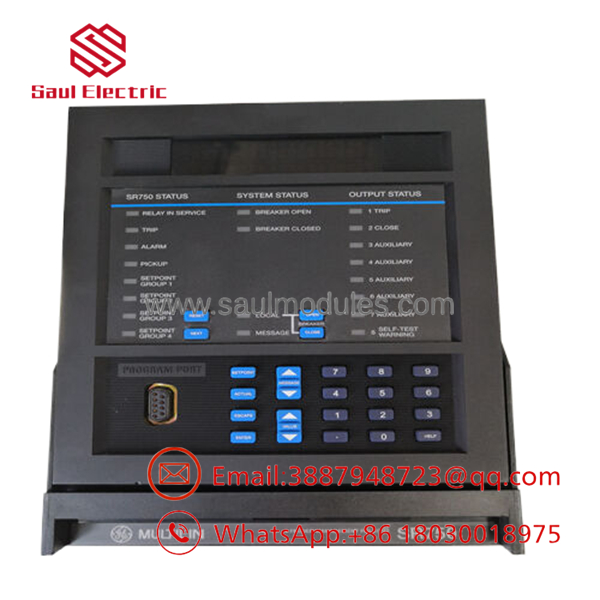
- SR750-P1-G1-S1-HI-A20-R-E
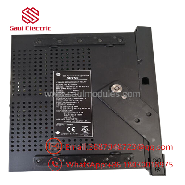
- SR750-P1-G1-S1-HI-A20-R-E
【Core Strategy 1: SOP Quality Transparency】
To eliminate the uncertainty associated with sourcing surplus and obsolete protection hardware, every inventory asset undergoes a multi-phase validation process prior to shipment. Test parameters and video documentation are recorded for each specific serial number and are available upon request.
1. Inbound Inspection & Traceability
- Source Verification: Every module is matched against OEM batch packing records and historical distribution data to confirm authenticity.
- Anti-Counterfeit Audits: Serial numbers and physical product badges undergo mechanical matching against factory formats. We flag and reject modules showing signs of component re-soldering or housing alterations.
- Visual Grading: Technicians verify the unit has no terminal oxidation, cracked bezel plastic, or UV discoloration on the front LCD window.
2. Live Functional Testing
- Test Bench Environment: Units are mounted into a genuine GE SR750 test enclosure tied to a secondary injection test set.
- Power-On Self-Test (POST): The relay must pass internal RAM/ROM integrity diagnostics upon power-up, with the “Relay In Service” green LED illuminating within standard boot limits.
- Signal Injection (I/O Validation): We execute full-scale current and voltage injection tests across all phase and ground inputs. Analog outputs are measured using a calibrated Fluke 115 multimeter to confirm accurate 4–20 mA scaling.
- Load Burn-In: The unit is placed under continuous monitoring on the auxiliary power rails for over 24 hours inside a thermal chamber to rule out infant mortality or intermittent component drift.
3. Electrical Parameter Testing
- Insulation Resistance: Using a 500 V Megger insulation tester, insulation resistance between separate current inputs, contact outputs, and ground rails is verified to exceed 10 MΩ.
- Ground Continuity: The chassis grounding path is mapped to ensure proper dissipation of fault energy.
4. Firmware & Configuration Verification
- Firmware Documentation: The firmware revision is extracted via EnerVista 750 software and noted on the final test sheet.
- Hardware State Backup: All physical jumpers and rear port dip switches are photographed and reset to factory defaults or custom user configurations depending on requirements.
5. Final QC & Packaging
- ESD Control: The relay is extracted from the test environment using grounded workstations and placed inside heavy-duty anti-static shielding bags.
- Corrugated Boxing: Double-wall corrugated boxing lined with high-density foam padding protects the drawout frame from mechanical shocks during global transit. A dated QC Passed certificate is fixed to the exterior seal.
Installation & Configuration Guide
Stage 1: Pre-Installation Preparation
- Estimated Time: 15 minutes
- ⚠️ Safety First: Open all circuit breakers supplying the primary feeder path. Lock out and tag out all auxiliary control power lines feeding the relay slot. Wait 5 minutes after disconnecting control power to allow internal capacitors to discharge completely.
- Tools Required: ESD wrist strap, PH1 and PH2 screwdrivers, digital multimeter, wire marker kit, and a smartphone for site records.
- Data Backup: Connect a laptop via RS232 or Ethernet to the existing relay. Open EnerVista 750 and execute a complete setpoint file export (
.750file extension). Document the specific IP addresses, subnet masks, and Modbus device IDs.
Stage 2: Removing the Old Module
- Estimated Time: 10 minutes
- Steps:
- Open the dust-tight front access door.
- Loosen the front retaining screws holding the inner drawout chassis to the outer cradle.
- Pull the drawout handle firmly outward to disengage the rear internal locking contacts.
- Slide the assembly straight out of the case. Do not twist or force the chassis, as this will warp the rear terminal mating fingers.
- Inspect the empty case interior for bent pins, dust loading, or signs of carbon arcing on the block contacts.
- ⚠️ Note: Retain the old chassis in a clean, dry area until the replacement unit is fully commissioned and online.
Stage 3: Installing the New Module
- Estimated Time: 15 minutes
- Steps:
- Wear a grounded ESD wrist strap connected to the substation ground bar.
- Compare the nameplates of both units to verify that the replacement is an exact hardware match (
SR750-P1-G1-S1-HI-A20-R-E). - Configuration Clone: Align any internal hardware jumpers or rear port address switch matrices to exactly match the configurations recorded during Stage 1.
- Align the new inner chassis with the guides of the existing enclosure shell. Push the unit steadily inward until the main drawout handle snaps home.
- Hand-tighten the front structural retaining screws to secure the module into the case.
- Self-Checklist:
- [ ] Drawout handle fully latched and flush.
- [ ] Retaining screws tightened down.
- [ ] Jumpers and dip settings verified against baseline photos.
Stage 4: Power-On & Testing
- Estimated Time: 20 minutes
- Pre-Power Check: Measure resistance across the rear auxiliary power inputs to verify there are no direct dead shorts on the DC control supply lines.
- Power-On Steps:
- Energize the auxiliary control power loop (do not close the primary breaker yet).
- Monitor the front faceplate. The green RELAY IN SERVICE LED must light up, and the alphanumeric display should cycle to its default metering screen.
- Connect the PC to the front RS232 interface. Upload the saved
.750setpoint configuration file using EnerVista software. - Verify that the firmware level matches the requirements of the system host. If communication timeout errors occur, re-verify the local serial or IP settings.
- Run a digital output simulation via software to verify that the trip and close contact paths cycle their respective circuits correctly before placing the unit online.
- ⚠️ Troubleshooting Note: A solid red TRIP or ALARM indicator immediately after boot typically points to an uncalibrated current loop mismatch or an invalid configuration script. Check the software event log for exact error strings.
【Core Strategy 2: Technical Pitfall & Survival Guide】
1. Firmware Revision Mismatch
A replacement unit may arrive with an updated or older firmware generation than your active master system expects. I have encountered situations where a technician swapped in a replacement relay only to have the regional SCADA host reject the communication loop for hours. The protocol mapping or internal register layout altered slightly between major firmware blocks, leading to persistent timeout faults. Always extract the baseline firmware index before extraction, and verify compatibility with your master control system before putting the feeder back into production.
2. DIP Switch & Jumper Misconfiguration
The rear serial port configuration and specific internal input scaling options rely on precise physical switch layouts. Assuming the new unit arrives pre-configured for your site needs is a common mistake. If the baud rate or terminal resistance configurations do not match the old unit, the network loop will drop out completely. Take a high-resolution photograph of the active module’s switch layout before pulling it from the panel. Mirror the positions onto the replacement unit exactly.
3. Terminal Block Contact Alignment
While the drawout design simplifies field maintenance, the internal mating fingers on the back of the chassis can suffer wear over decades of operation. ❗ Never smash a drawout unit into its enclosure. If the alignment guides are worn, force will bend the rear connection fingers, causing erratic open circuits on critical CT inputs. Slide the module home with firm, linear pressure. If you encounter resistance, stop, extract the module, and check the alignment of the connector blocks.
4. Auxiliary Power Supply Loading
The “HI” power variant covers a wide voltage envelope, but aged DC battery systems or heavily loaded control loops can exhibit severe voltage drops during substation switching operations. When you populate a rack with multiple high-density modules or hang secondary external transducers off the 4–20 mA analog outputs, the control circuit’s current draw increases. Ensure your 125 VDC or 250 VDC auxiliary battery supply retains at least a 20% margin to prevent the relay from rebooting during heavy fault conditions.
5. Electrostatic Discharge (ESD) Hazards
The internal logic boards of the SR750 contain high-density components sensitive to static electricity. I once watched an out-of-state field technician pull a replacement board out of its packaging in sub-zero winter temperatures without an ESD strap. The static discharge pin-pricked the processor bus; the unit booted fine on the bench but failed completely under load testing hours later. Work only on grounded surfaces and use static shielding wraps during transport.
Keep these deployment checks in mind during your next substation outage, and you will prevent the vast majority of unexpected commissioning delays.
Frequently Asked Questions (FAQ)
Can I hot-swap this relay module while the feeder circuit is live?
No. While the drawout structure disconnects the electronic chassis cleanly, removing the module while the primary feeder is carrying load will instantly open-circuit your current transformers (CTs). Opening a live CT secondary circuit generates lethal, thousands-of-volts arcs that will destroy the internal automatic shorting bars in the outer case and pose severe physical risks. You must isolate control power and dump primary feeder loads before extracting the inner chassis.
The model number on my existing relay ends in an older suffix. Is this “E” version compatible?
Yes, in nearly all industrial settings. The “E” suffix identifies the enhanced display package, which often includes integrated 10Base-T Ethernet communication hardware. The base protective relay functions, form-factor framing, and backplane contact pin-outs are backward compatible with standard older drawout frames. However, you must update your EnerVista software workspace to recognize the new hardware configuration profile before attempting to download your old setpoint files.
Will I lose my protection settings and historical log records when I pull the old CPU out?
The active protective profiles and system settings are saved directly to the non-volatile EEPROM memory within the drawout chassis itself. The outer case structure contains only terminal blocks and passive wiring. When you replace the inner chassis, the new unit will contain factory default parameters. You must manually download your backed-up .750 configuration file into the replacement relay using the EnerVista utility to restore your specific operational parameters.
Why is your pricing for this New Surplus unit lower than the OEM factory list price?
Our inventory is sourced via industrial surplus asset liquidation, plant modernizations, and cancelled project backups. Because these units are new surplus stock rather than direct factory shipments, we price them to account for market availability and the transition from original factory distribution channels. Every unit is backed by our full industrial warranty and verified via live injection test rigs to perform to original technical specifications.
How do I check for a communication failure if the relay won’t talk to my EnerVista software?
Start by verifying your interface cable pinout. The front RS232 port requires a straight-through serial link, not a null-modem configuration. If you are communicating via the rear Ethernet port, check that the link LED on the rear panel is illuminated. If it is dark, verify your switch connection or network patch cable. If the hardware connection is good, use the front panel keypad to navigate to the S1 750 SETUP menu and verify that the baud rate, slave address, and IP properties match your PC settings exactly.



 Start Chat


