





Description
Key Technical Specifications
| Parameter | Value / Specification |
| System Family | GE Multilin Universal Relay (UR) Platform |
| Card Identifier | UR6AV / UR-6AV |
| Digital Inputs | 8 high-speed discrete inputs |
| Input Scan Rate | 0.5 ms high-frequency sample resolution |
| Form-A Outputs | 2 standard contacts (Normally Open – NO) |
| Form-C Outputs | 1 changeover contact (NO / NC / Common) |
| Latching Channels | 2 magnetically/mechanically non-volatile latching outputs |
| Form-A Operating Speed | High-speed activation response time < 4 ms |
| Logic Orchestration | Full integration with FlexLogic™ engine (up to 1,024 programming lines) |
| Contact Isolation | Complete galvanic isolation from structural system signal ground |
| Monitoring Option | Factory integrated hardware voltage checking across Form-A traces |
| Manufacturing Origin | Markham, Ontario, Canada |
Product Introduction
The GE Multilin UR6AV is a high-performance Digital Input/Output module card engineered explicitly for the modular Universal Relay (UR) series protection and control platform. Designed to expand the discrete interface footprint of specialized feeder, generator, and transmission protection architectures (such as the L90, B30, or F60), the UR6AV provides a highly versatile contact mix. It packs 8 diagnostic digital inputs and a versatile array of 5 output contacts—including high-speed Form-A, standard Form-C, and bi-stable latching relays—onto a single slide-in rack module.
Operating with sub-millisecond precision, the UR6AV features an input scan resolution of 0.5 ms and a Form-A activation timeline under 4 ms, rendering it well-suited for high-availability trip execution loops. When dropped into the UR chassis, the card ties into the native FlexLogic™ programmable logic engine. This connection allows utility engineers to configure custom interlocking rules, breaker state mapping, and automated diagnostic schemes directly within the substation’s primary protection zone.
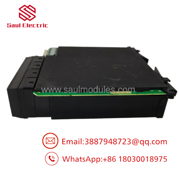
- UR6AV
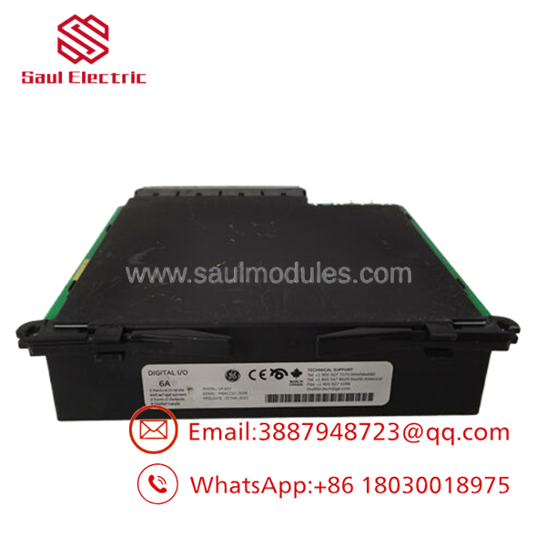
- UR6AV
Installation & Configuration Guide
Stage 1: Pre-Installation Preparation (Estimated Time: 15 minutes)
- ⚠️ Safety First: The handles high-speed trip signals that connect to primary circuit breaker coils. Never unseat or insert an I/O card while the host Universal Relay chassis is powered. Turn off the auxiliary control breaker supplying power to the relay chassis. Short-circuit all adjacent current transformer (CT) secondary test blocks to eliminate inductive high-voltage hazards.
- Tools Required: Grounded static-prevention wrist strap, medium flathead screwdriver, laptop configured with the relevant version of EnerVista UR Setup software, serial or Ethernet hookup patch cords.
- Data Backup: Establish a data session with the target relay using EnerVista UR Setup before dropping power. Upload and archive a full backup copy of the parameter settings, firmware maps, and custom FlexLogic profiles active on the machine.
Stage 3: Removing the Old Card (Estimated Time: 5 minutes)
- Affix your grounded anti-static wrist strap to an unpainted, structural framework bolt on the cabinet housing.
- Label and index every field wire landed on the rear terminal connector block before disconnecting them to avoid cross-wiring errors during re-installation.
- Remove the terminal strip plugs from the backplane connectors of the module slot.
- Turn the upper and lower captive module retaining screws counterclockwise until they unthread cleanly from the chassis face.
- Pull the module straight outward using the built-in card edge pulls. Keep the assembly completely parallel with the tracking slots to prevent scratch damage to neighboring modules. Slide the extracted card into an ESD protective shielding wrap.
Stage 3: Installing the New Card (Estimated Time: 10 minutes)
- Unpack the replacement module, taking care to avoid touching raw electronic traces or rear connector pins.
- Align the plastic tracks on the top and bottom of the card guide with the open channel slot tracks inside the UR chassis backplane frame.
- Slide the card smoothly back into the slot until the rear multi-pin plug engages flush with the high-density internal backplane bus.
- Push the captive mounting screws home and tighten them down evenly with your flathead screwdriver to ensure a secure, vibration-resistant fit.
- Re-engage the terminal blocks, plugging the labeled field wires back into their original connector blocks.
Stage 4: Power-On & Commissioning (Estimated Time: 20 minutes)
- Re-energize the auxiliary control power lines feeding the Universal Relay chassis frame.
- Watch the front panel HMI interface during the boot sequence:
- The green In Service light should cycle back to solid green.
- ⚠️ Troubleshooting: If a hardware configuration mismatch error or a solid amber Self-Test Error alert appears, open EnerVista to verify that your system architecture configuration tree matches the newly detected module profile.
- Open EnerVista UR Setup, navigate to the hardware configuration status page, confirm that slot tracking identifies the module correctly, and download your archived configuration file to restore original logic assignments.
Frequently Asked Questions (FAQ)
Can I hot-swap this card while the Universal Relay is online?
No. The GE Multilin UR platform does not support the hot-swapping of internal I/O modules while the backplane data bus is active. Pulling a card under power causes electrical transients along the interior logic buses, which will immediately lock up the core CPU module or trigger an unintended safety trip response. Always isolate the chassis power supply before swapping a module.
What is the specific purpose of the 2 Latching Outputs on this module?
The latching outputs on the are bi-stable mechanical relays that retain their last commanded position (either Open or Closed) even if auxiliary control power to the relay chassis is completely lost. This is a critical feature for building lock-out relay functions (86 device automation) and maintaining process state flags through emergency power brownouts without relying on continuous battery current.
Why does EnerVista show a “Hardware Mismatch” fault after I insert the replacement module?
This alert occurs because the internal memory on the main CPU processor card is still looking for the unique electronic identifier or serial tracking tag of the old board. To clear this fault, navigate to the “Hardware Configuration” tab inside the EnerVista UR Setup workspace, select the “Read Architecture from Relay” discovery command to update the internal configuration registry, and send the modified settings down to the relay.
Are the 6 A contact current limits safe for direct circuit breaker trip coil orchestration?
Yes, the output contacts on the are rated to handle up to 6 A of continuous current. This makes them strong enough to drive standard circuit breaker trip and close coils directly, provided the inductive voltage transients stay within the specified operating thresholds of the UR chassis framework. For unusually large or high-draw inductive trip coils, it is best practice to wire an external interposing relay to prevent premature contact wear.
Are these modules current production factory components?
While the Universal Relay series remains an active cornerstone of global substation protection architecture, individual module sub-assemblies can face manufacturing updates or long lead times from the OEM. Our inventory consists of New Original / New Surplus stock—unused factory components sourced directly from system upgrades, distribution liquidations, or warehouse overstock. This provides access to genuine replacement parts with no factory lead times.



 Start Chat


